Robotic kinematics
-
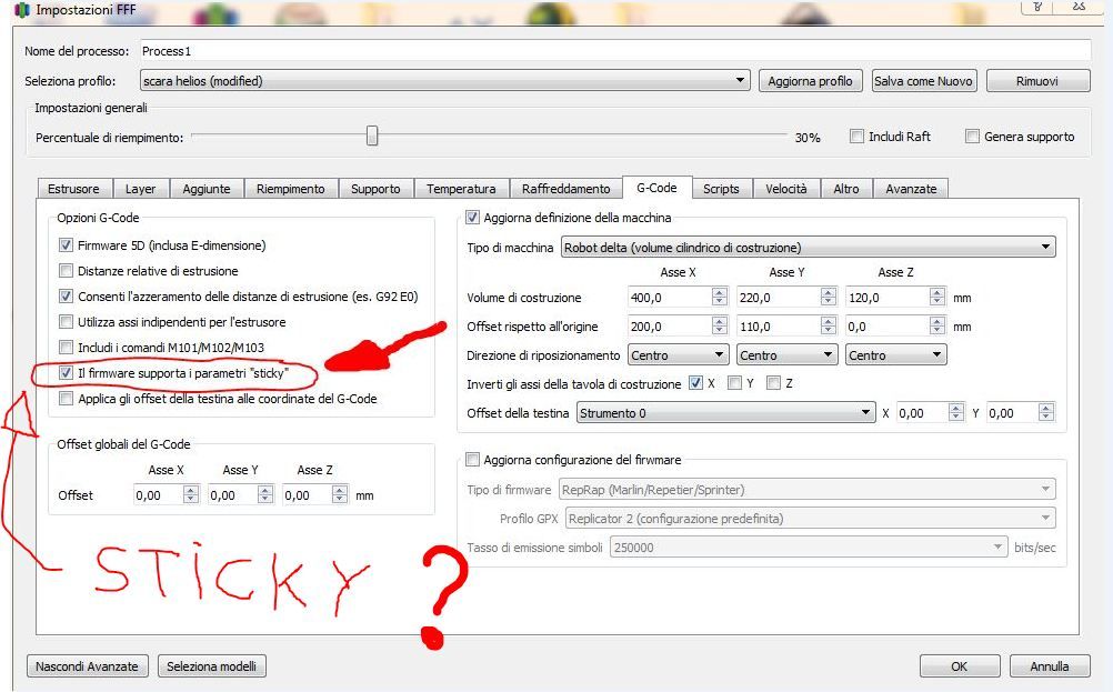
the sticky parameter is a 3d simplify function, I don't know exactly what it is used for.I just noticed that when it is active it can start the print and once stopped with stop it is possible to move the motors with G1 commands or with the jog control of simplify 3d, without the sticky function the print does not start and the gcode scrolls towards the end and it is not possible to move the motors.

after homing I send M114 and it replies:
X 500 Y0 Z100 U0 V5.005 I don't understand why (V 5.005) V always marks this value even if you change the arm lengths or other parameters, maybe it's a simplify 3d problem that doesn't handle V axis well !!could it be like you said arm 5 is zero long?
this and homeall
M913 X50 Y50 Z50 U50 V50 ;RIDUZIONE CORRENTE MOTORE PER HOMING
; casa x
G91 ;movimento relativo
G1 H1 X-200 F800
G1 H2 X10
G1 H1 X-20 F300; casa y
;G91 movimento relativo
G1 H1 Y-200 F800
G1 H2 Y10
G1 H1 Y-20 F300; casa z
; G1 H2 Z2 F3000
G1 H1 Z-200 F2000;casa U
;G91; movimento relativo
G1 H1 U-40 F1000
G1 H2 U15 F800
G1 H1 U-10 F500;casa V
;G91; movimento relativo
G1 H1 V-40 F1000
G1 H2 V15 F800
G1 H1 V-10 F500G90 ;torna alla modalità assoluta
M913 X100 Y100 Z100 U100 V100 ;RIPRISTINO CORENTE MOTORE FINE HOMING
however I think that now I would need a prototype of a robot arm, because with the duet 3 connected only to motors, it is not much use !!
-
@tony73 said in Robotic kinematics:
G1 H1 X-200 F800
G1 H2 X10
G1 H1 X-20 F300G1 H1 sets the position to the M208 mininum position when the endstop is hit, and for the other axes too. When you start with a G1 then, one or more of the 5 axes will try to rotate into a direction where it is beyond the limit.
What you need to do is after hitting the endstops, move all axes back to some middle positions between the angle limits, before starting G1. And the endstops will often not be at the minimum M208 position, so after hitting the endstop, set the position with G92.
I've started a homing document, where I describe the hole procedure: https://duet3d.dozuki.com/Wiki/Homing_for_a_FiveAxisRobot?revisionid=HEAD
I agree it is easier with a prototype.
My first version was from wood, but was too unstable. I am currently building it with aluminium, but have technical problems to bore exact 16 mm holes. I ordered the necessary drills, but this will take another 2-3 days. I didn't want to tell you the building plan until I know if the next version is stable enough. (In case you want to clone, I use aluminium 20x10x2 mm for the outer arm elements, and 100x20x2 aluminium for stiffness).
PS The M114 Z100 value is already outside of the M208 limits (Z shall be 0 or negative, arm 3 going down), this will prevent for a G1 command to execute.
PS2 the V value is axis 5 angle and depends on the P strategy. It will change if axis 1 angle is changed, so it depends on the X value also. X 500 means 360+ 140 degree, so somewhere rotated left "rotated behind". (in reality the 360 would mean displacing all the cables and filament).
PS3 my test program included arm5length==0, so it's no problem to set it to 0.
-
@JoergS5
I want to understand well! about X 500 you say it's 360 + 140 degrees! x 500 and given by M 114 after homing (x500 y0 z100 u0 v5.005) are these Cartesian coordinates or degrees? -
@tony73 M114 reports axis coordinates, i.e. in this case degrees. (I looked into the source code, GetCurrentCoordinates() in GCodes.cpp)
-
@JoergS5
before I changed M208 when using A-45: 45: 0: 140: -140: 0: -170: 170: -135: 135
the result of M114 after homing were Cartesian coordinates not degrees, right or wrong to understand? -
@tony73 I didn't change M114's code, so it was always axis/stepper/motor positions. With cartesian/CoreXY it is in mm, with scara and robot the unit is degrees. The values are axis values.
What I changed is the interpretation and meaning of M208. After analyzing the code, I saw that M208 checks against machine positions, so in the case of scara/robot, against degree values. The M208 degree interpretation matches G1 H1 setting the endstop position to the M208 min value in degree also, so all makes sense now (however H1 value itself often is not correct).
I am also confused by the mix of the XYZ values often. It was a bad design decision some years before when G-Code was defined to mix the meanings. I analyzed it a bit here: https://forum.duet3d.com/topic/17222/duet3d-3-custom-delta-printer-inconsistant-motor-problems?_=1594453426871
-
test to understand
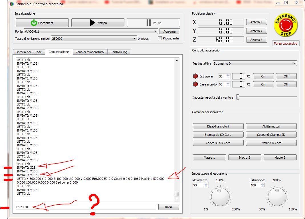
i did G28
called M114 answer after homing X500 Y0 Z100 U0 V5.005
if I send G92 X40 what are degrees for actuator X 40 or position X 40 on the Cartesian plane?
-
@tony73 according to https://duet3d.dozuki.com/Wiki/Gcode#Section_G92_Set_Position they are axis positions, ie degrees. The code is in SetPositions in GCodes3.cpp and confirms it.
When you make G92 X40 and then M114, it should show X40 as value. Testing without prototype: trigger all endstops and set the axis positions to the middle values (middle of the m208 limits) of the axes with G92. Then you should be able to move around a bit.
-
i did this test, this is M208 which i am using in config.g
M208 X-45.0: 45.0 Y0.0: 140.0 Z-140.0: 0.0 U-170.0: 170.0 V-225.0: 225.0
i did the homing G28
M114 tells me as always X500 Y0 Z100 U0 V5.005i sent G92 X0 Y70 Z-70 U0 V0
and fair as an average? or wrong?
because M114 marks X0 Y70 Z-70 U0 V0 but the motors don't move !!
I found another way to move the motors. this and M669 of config.g
M669 K13 X0.0: 0.0 Y0.0: 0.0 Z100.0 L200.0: 200.0: 100.0: 0.0 R0 P3 C0
this and M114 after homing
X500 Y0 Z100 U0 V5.005I thought that X500 was the sum L2 + L3 + L4 which would be 200 + 200 + 100, because in the instructions in the homing position the robot is stretched along the X axis
the sum of L2 + L3 + L4 is 500mm but L4 actually has to work vertically by removing L4 from 500 resulting in 400 which should be the maximum X coordinate reachable by the robot perhaps a little less than 400 example 396!
i sent after homing
G92 X390 Y0 Z100 U0 V0motors move G1/G2/G3 XYZ respond Z goes up over 200 I don't remember how much and goes down over 0 goes negative Y I don't remember how much in max and min, X is max 396 min 93,
I repeat the motors move, but not having a robot, I can't see anything else!help me to understand !
-
@tony73 you mix up X values:
M114 X is an angle. The sum of L2+L3 are coordinates,
390 is reachable because L2+L3 > 390.
The real maximum is less, because the printable area has the form of a donut: in the middle 390 is reachable, but with high or low Z it is less (arms 2 und 3 need some of their distance for the Z change).Your G92 settings look ok (but you could calculate and set the correct angle 4 to be vertical), you should start with smaller G1 movements to be sure they are in the printable area.
Angle 4 can be calculated:
angle 4 = -90 - angle2 - angle3
Your Z should not be positive (=up), but always negative. This means arm 3 goes down after arm 2 went up.The M669 Z value (= z height of axis 2) has nothing to do with the M114 Z (and G92 Z) value (axis 3 angle).
-
the G92 that seems valid to you and this? G92 X390 Y0 Z100 U0 V0
I tried again but X is around 387.400 (G92 X387.400 Y0 Z100 U0 V0) as you said, not always reachable due to the position of Y and Z
however the engines are moving, X390 was not good!
this G92 X387.400 Y0 Z100 U0 V0 and where would a hypothetical extruder be found on the Cartesian plane?
my doubt, V0 can go! but U0? is only X Y Z considered?when you are ready I need to see your robot, maybe a video of the homing to understand better !!
-
@tony73 no, I meant the G92:
G92 X0 Y70 Z-70 U0 V0
looks ok. G92 X390 is a too high angle.As my prototype takes too much time (orders missing), I'll make a very simple version at the weekend with R0 mode and take it to explain it.
-
ok! it seems like a great idea!
-
@tony73 I'll build it with the same properties like your parameters, so we can discuss all.
-
Hello! how is the construction of the robot going?
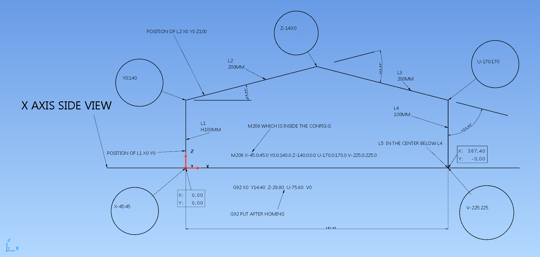
i tried to graph a situation with G92 to position the arm after homing, hope it is clear enough. calculated the degrees of a position X 387.4 Y0 Z0 on M669 of my config.g but I don't understand, if G92 are degrees and the calculation is right, if you can understand tell me if it's right or wrong, the motors should move, but instead simplify 3d answers me like this, Error: G1 / G2 / G3: intermediate position outside machine limits.
the G92 I put after homing and G92 X0 Y14.4 Z-28.8 U-75.6 V0
it looks like a little house!
the degrees of the graph are L2 14.40 L3 -28.80 L4 -75.60
-
@tony73 I am proceeding with boring my 1000 holes into aluminium, but not finished. I expect Tuesday. (boring holes without cnc is a penalty)
The graphic looks fine, the angles look all ok. Which G1 command do you want to execute? If it's G1 X300, then are you in absolute coordination mode or relative? Because if relative, it wants to move to 687,40, which is out of reach.
To exclude that it's a Simplify3D problem, can you execute it in the Duet Web Control (DWC)?Absolute mode is set with G90
Can you please check M114 after homing and G92?
-
@JoergS5
purtroppo non avevo mai considerato il G90 G91 , se ho capito provando a mandare esempio: G1 X200 in modalita relativa G91 , tenterebbe di andare a X 587.40 ( X 387.40 + 200 ) , devo ricordarmi di G90 e G91 !
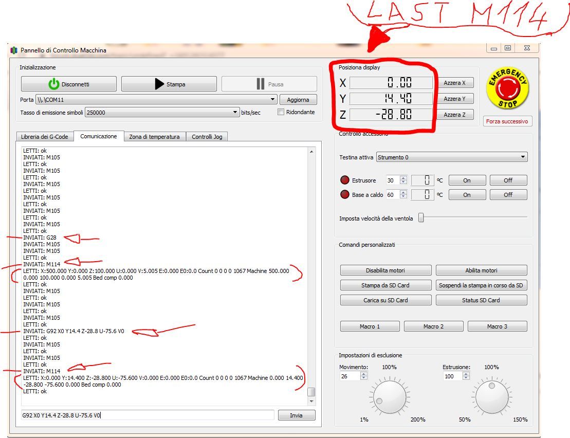
ho provato a inviare G90 prima di un comando G1 ma i motori purtroppo non si muovono.questo nella foto e G28 seguito da M114 che dice X500 Y0 Z100 U0 V5.005 dopo inviato
G92 X0 Y14.4 Z-28.8 U-75.6 V0 rifatto M114 risposta X0 Y14.40 Z-28.80 U-75.60 V0.0
LA COSA STRANA e che in alto a destra lindicatore degli assi di simplify 3d da come posizione del piano cartesiano X0 Y14.40 Z-28.80 che e uguale ai gradi di G92no ho ancora mai usato DWC , ma mi documento e provo !!

-
Sorry for barging in. But...
If you were to describe the robot as a number of transformation matrices (https://en.wikipedia.org/wiki/Denavit–Hartenberg_parameters) you could describe any serial robot with any number of axis. Even a serial scara could fit in this (except the bed).
Matrices are very nice to work with.
Combine this with the matrix defined cartesian and you can describe any combination of linear cartesian and serial rotary kinematics. What a dream

-
@bondus I know the matrix calculations, but I wanted to develop the algorithms from scratch and to have additional parameters like bending.
-
@tony73 you seem to have set G90 at the end of your homing file.
I'll check your procedure with my prototype tomorrow.