Duet3D Logo Duet3D
    • Tags
    • Documentation
    • Order
    • Register
    • Login

    Adding status LEDs to microswitch endstop for tool change

    Scheduled Pinned Locked Moved
    Duet Hardware and wiring
    2
    3
    151
    Loading More Posts
    • Oldest to Newest
    • Newest to Oldest
    • Most Votes
    Reply
    • Reply as topic
    Log in to reply
    This topic has been deleted. Only users with topic management privileges can see it.
    • copperbricksundefined
      copperbricks
      last edited by Phaedrux

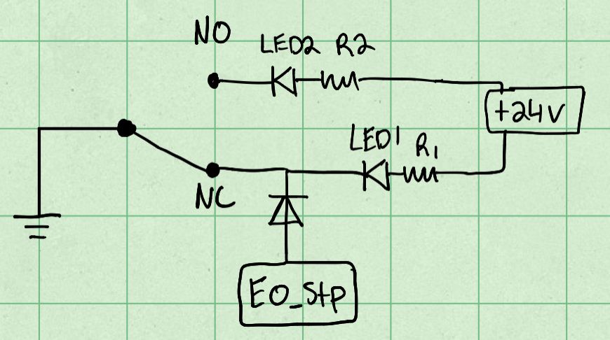
      I have a homebuilt Toolchange printer I'm close to finishing and recently added a tool status microswitch to the toolhead to avoid picking up a tool with one already attached and similar errors. I'd also like to add LEDs to indicate the status- LED2 on for tool attached, LED1 for no tool attached. Is the wiring shown below suitable? The only thing I'm not sure on is having the step pin connected to 24v, in my diagram I have a diode but I'm not sure if that would work.

      IMG_0340.jpeg

      Alternately I can just use two GPIO pins and daemon.g to update the LEDs status but this seems a little simpler.

      Thanks

      1 Reply Last reply Reply Quote 0
      • T3P3Tonyundefined
        T3P3Tony administrators
        last edited by

        I checked this with @dc42: This should be ok, diode should preferably be Schottky to preserve the noise margin.

        www.duet3d.com

        copperbricksundefined 1 Reply Last reply Reply Quote 0
        • copperbricksundefined
          copperbricks @T3P3Tony
          last edited by

          @T3P3Tony Got it, thank you! I'll make sure it's a schottky diode.

          1 Reply Last reply Reply Quote 0
          • First post
            Last post
          Unless otherwise noted, all forum content is licensed under CC-BY-SA