double extruder motor - g.code?
-
hey,
I want to have 2 motors on each filament.
One motor for the direct drive extruder, one motor for changing the filament and helping getting filament from a heavy filament roll (10kg).
Does anybody knows what I have to change on the g code?
Driver 1 + Driver 0 or
Driver 2 + Driver 0 Must work together all the time. Same steps etc.
Drivers areon the expansion board.
Duet3thanks
R.G.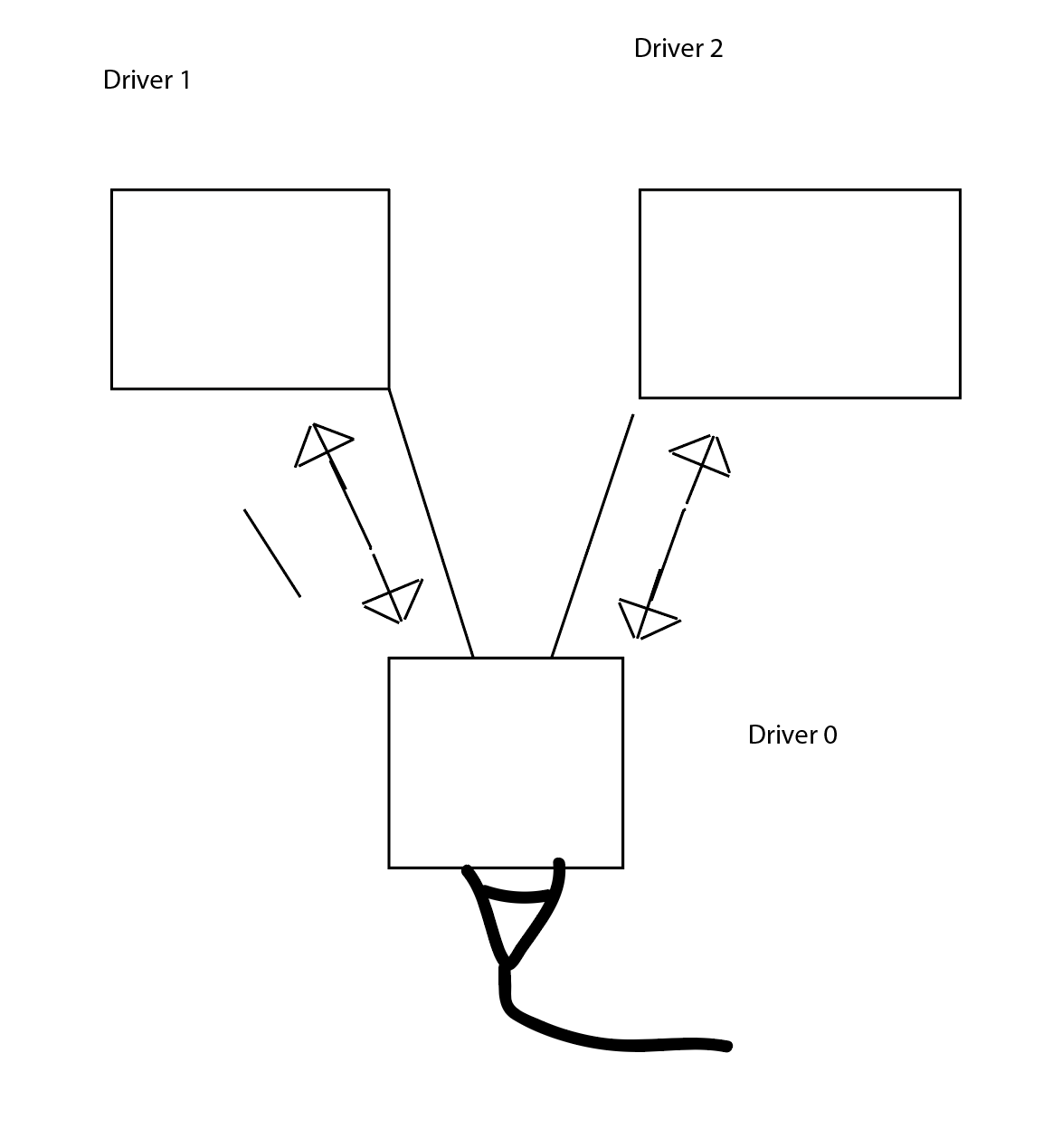
; Configuration file for Duet 3 (firmware version 3) ; executed by the firmware on start-up ; ; generated by RepRapFirmware Configuration Tool v3.1.3 on Tue Jun 23 2020 22:36:44 GMT+0200 (Mitteleuropäische Sommerzeit) ; General preferences G90 ; send absolute coordinates... M83 ; ...but relative extruder moves M550 P"Duet 3" ; set printer name ; Drives M569 P0.0 S1 ; physical drive 0.0 goes forwards M569 P0.1 S1 ; physical drive 0.1 goes forwards M569 P0.2 S1 ; physical drive 0.2 goes forwards M569 P0.3 S1 ; physical drive 0.3 goes forwards M569 P0.4 S1 ; physical drive 0.4 goes forwards M569 P0.5 S1 ; physical drive 0.5 goes forwards M569 P1.0 S1 ; physical drive 1.0 goes forwards M569 P1.1 S1 ; physical drive 1.1 goes forwards M569 P1.2 S1 ; physical drive 1.2 goes forwards M584 X0.0 Y0.1 Z0.2:0.3:0.4:0.5 E1.0:1.1:1.2 ; set drive mapping M350 X16 Y16 Z16 E16:16:16 I1 ; configure microstepping with interpolation M92 X160.00 Y160.00 Z1600.00 E375:375:375 ; set steps per mm ; set steps per mm M566 X900.00 Y900.00 Z12.00 E120.00:120.00:120.00 ; set maximum instantaneous speed changes (mm/min) M203 X6000.00 Y6000.00 Z180.00 E1200.00:1200.00:1200.00 ; set maximum speeds (mm/min) M201 X500.00 Y500.00 Z40.00 E250.00:250.00:250.00 ; set accelerations (mm/s^2) M906 X1400 Y1400 Z3000 E1000:1000:1000 I30 ; set motor currents (mA) and motor idle factor in per cent M84 S30 ; Set idle timeout ; Axis Limits M208 X0 Y0 Z0 S1 ; set axis minima M208 X700 Y700 Z800 S0 ; set axis maxima ; Endstops M574 X2 S1 P"!io3.in" ; configure active-high endstop for high end on X via pin !io3.in M574 Y2 S1 P"!io0.in" ; configure active-high endstop for high end on Y via pin !io0.in ; Z-Probe M558 P9 C"io4.in" H10 F200 T1800 ; set Z probe type to bltouch and the dive height + speeds M950 S0 C"io4.out" ; create servo pin 0 for BLTouch G31 P25 X0 Y-36 Z2.5 ; set Z probe trigger value, offset and trigger height M557 X10:600 Y10:600 S200 ; define mesh grid ; Heaters M308 S0 P"temp0" Y"thermistor" T100000 B4138 ; configure sensor 0 as thermistor on pin temp0 M950 H0 C"out0" T0 ; create bed heater output on out0 and map it to sensor 0 M307 H1 S1.00 ; disable bang-bang mode for the bed heater and set PWM limit M140 H0 ; map heated bed to heater 0 M143 H0 S90 ; set temperature limit for heater 0 to 90C M308 S1 P"temp1" Y"thermistor" T100000 B4138 ; configure sensor 1 as thermistor on pin temp1 M950 H1 C"out1" T1 ; create nozzle heater output on out1 and map it to sensor 1 M307 H1 B0 S1.00 ; disable bang-bang mode for heater and set PWM limit ; Fans M950 F0 C"out8" Q500 ; create fan 0 on pin out3 and set its frequency M106 P0 S1 H-1 ; set fan 0 value. Thermostatic control is turned off M950 F1 C"out7" Q500 ; create fan 1 on pin out7 and set its frequency M106 P1 S1 H-1 ; set fan 1 value. Thermostatic control is turned off M950 F2 C"out8" Q500 ; create fan 2 on pin out8 and set its frequency M106 P2 S1 H T45 ; set fan 2 value. Thermostatic control is turned on ; Tools M563 P0 D0 H1 F0 ; define tool 0 G10 P0 X0 Y0 Z0 ; set tool 0 axis offsets G10 P0 R0 S0 ; set initial tool 0 active and standby temperatures to 0C ; Custom settings are not defined M671 X185:185:615:615 Y-125:925:925:-125 S2.5 ; Miscellaneous M501 ; load saved parameters from non-volatile memory M911 S10 R11 P"M913 X0 Y0 G91 M83 G1 Z3 E-5 F1000" ; set voltage thresholds and actions to run on power -
@barbarossa-cologne
To run 2 extruder motors in "push-pull" configuration you simply map both motors to the tool and set the mixing ratio to 1:1.
Assuming you have 3 extruder motors mapped as you have them in your M584. Then the first motor is extruder drive 0, the second is extruder drive 1 and the third is extruder drive 2. Assuming the first one is common (driver 0) then you define the tool like this....
M563 P0 D0:1 H1 F0 ; define tool 0
and set the mixing ratio like this
M567 P0 E1.00:1.00To change extruder drives, you now have 2 options and to switch between them, the best way might be to use macros. The first option is simply to change the drive mapping. So it becomes
M563 P0 D0:2 H1 F0 ; define tool 0Or you can create a second tool as above but change P0 to P1 so the second tool becomes tool 1 and when you change to a different spool, you change the tool.
Actually, there is also a third option and that is to have a single tool but map all drives to it like this:
M563 P0 D0:1:2 H1 F0
and then change the mixing ratio so for one reel of filament you would use:
M567 P0 E1.00:1.00:0.00and for the second reel of filament you would use
M567 P0 E1.00:0.00:1.00HTH
-
@deckingman said in double extruder motor - g.code?:
M563 P0 D0:2 H1 F0 ; define tool 0
I would prefer the option with
:M563 P0 D0:2 H1 F0 ; define tool 0with adding the second tool it´s :
M563 P0 D0:2 H1 F0 ; define tool 0
M563 P1 D0:2 H1 F0 ; define tool 1Is this correct?
thanks for the great expalantion!!
Richard -
@barbarossa-cologne said in double extruder motor - g.code?:
@deckingman said in double extruder motor - g.code?:
M563 P0 D0:2 H1 F0 ; define tool 0
I would prefer the option with
:M563 P0 D0:2 H1 F0 ; define tool 0with adding the second tool it´s :
M563 P0 D0:2 H1 F0 ; define tool 0
M563 P1 D0:2 H1 F0 ; define tool 1Is this correct?
thanks for the great expalantion!!
RichardErr no. Your two tool definitions are identical so that won't work. With reference to your sketch, you have extruder drive 0 as "common", and driver 1 is the left hand filament and driver 2 is the right hand filament. So your two tool definitions should be:
M563 P0 D0:1 H1 F0 ; define tool 0
M563 P1 D0:2 H1 F0 ; define tool 1That is to say, one tool uses extruder 0 and extruder 1, the other tool uses extruder 0 and extruder 2.
-
ok....
I´ll try and tell you if it works!
thank you for the great answer.
LG
Richard -
This post is deleted! -
This post is deleted! -
@deckingman
It´s working..
Thanks a lot!! -
@barbarossa-cologne said in double extruder motor - g.code?:
@deckingman
It´s working..
Thanks a lot!!
-
@deckingman thanks for all your knowledge and helpfulness on this forum!
I'm thinking of making a MMU2 type multi-material setup that's run via the duet and a duex5 so this thread has been super helpful!
I have a BMG that is currently set up as direct drive, and i would like to keep it where it is so that i have the excellent extrusion control that it gives me.
My question is: do both drives need to be set to the same steps/mm ?
the BMG is 3:1 and the mmu plans that I'm looking at are directly driven by hobs off the stepper shaft. can i set that up with m92 since (im assuming) I'll need to define the additional stepper as U or V axis
Thanks in advance!