
Best posts made by dutti
-
RE: G32 Error:´´ Z probe was not triggered during probing move´´posted in Firmware installation
@droftarts
G32 is working perfect. Also the normal Z probe with the BL Touch!!!
Thank you a lot!!!!")
-
RE: electromagnet for tool dockposted in Tuning and tweaking
@jay_s_uk
The guy from the magnet shop told me this magnet is not getting hot. I think i give it a try - already bought 2...
I hope the best -
RE: PT1000 not working. no heatbed in DWC.posted in Duet Hardware and wiring
@phaedrux
Ok it´s working, now!!
thank you so much. sry for beeing stupid and frustrated. Usally the duets are doing what I want from them!!thanks a lot!!!
-
RE: DUET 3 broken?posted in Duet Hardware and wiring
@phaedrux
ok.... that has worked. Also verify the new software.
Latest posts made by dutti
-
RE: Crazy temperture - bug?posted in Duet Hardware and wiring
@dc42
ah what I forgot to say.. the tool was completly cold.
I´ve never printed with more than 220 degree.
with the original e3d pt1000 I have the temperature you see on the picture. with a german pt 1000 I have something with 500.
I only changed the toolboard and now everything works fine.
Same configuration and sensor...KR
Richard -
Crazy temperture - bug?posted in Duet Hardware and wiring
hey lovely community
I have the problem that tool one shwos crazy temperatures... also different temperatures with using different pt1000 BUT ONLY wrong temperatures between 300 and 500 degreee.
So it is really connected to the toolboard..I was printing with this tool completly fine for lots of prints and I changed nothing.
I updated all boards but I have to may solve the problem but that hasn´t worked.
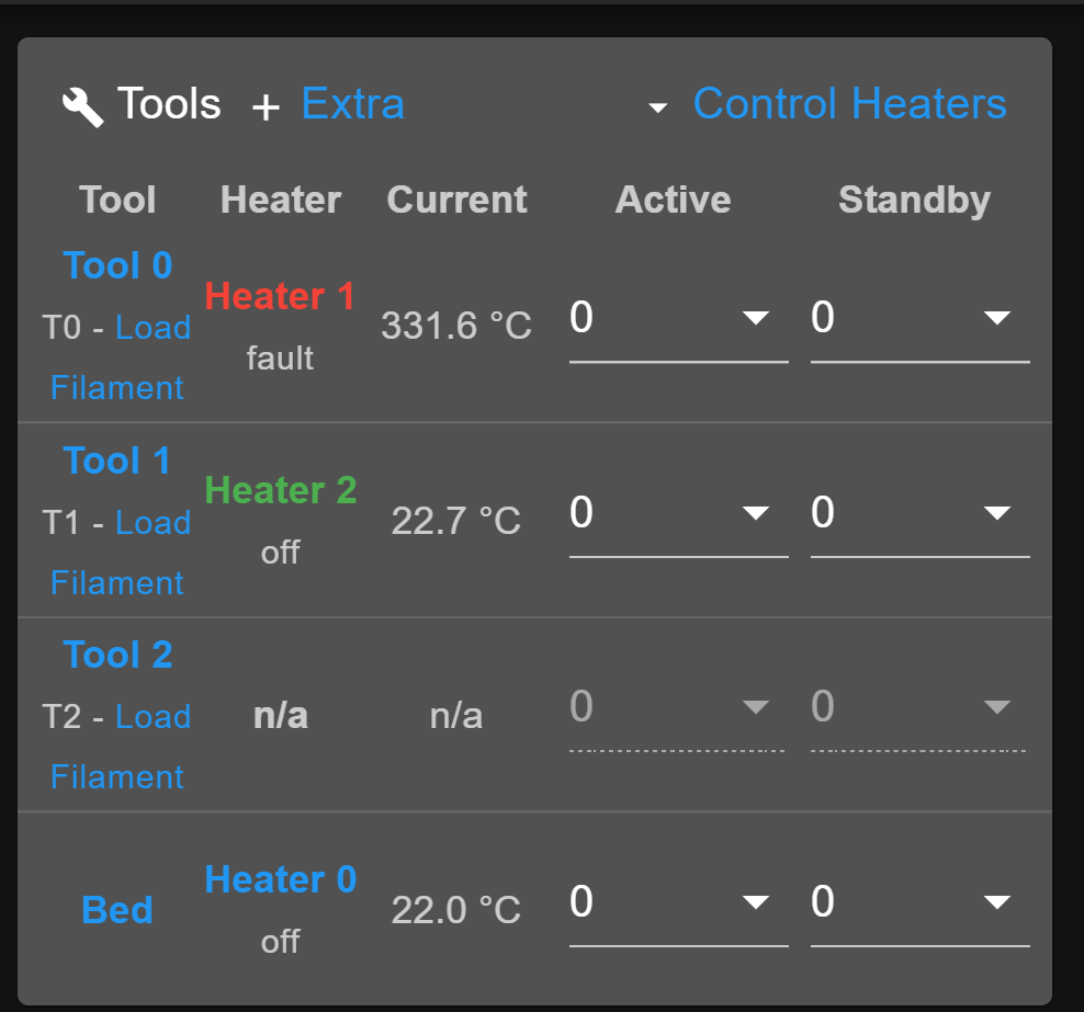
Then I found this....

May anybody knows this problem?
R.G.
-
RE: electromagnet for tool dockposted in Tuning and tweaking
@dc42
Yes it's should be 2kg but if I really need them... I'm not sure, yet.
I'll power them from the mainboard duet 3 or expansion board.
I guess I can choose the voltage?
What would be the best option to connect it? To the fan outputs?
Richard -
RE: electromagnet for tool dockposted in Tuning and tweaking
@fcwilt
the magnet is holding the tool directly. the tool has a small plate.. so in this case it should hold it while it´s not printing.I found this which maybe I can take for my own magnet system?
https://miscsolutions.wordpress.com/2020/06/06/improvements-to-the-hemera-tools/
Richard
-
RE: electromagnet for tool dockposted in Tuning and tweaking
@jay_s_uk
The guy from the magnet shop told me this magnet is not getting hot. I think i give it a try - already bought 2...
I hope the best -
electromagnet for tool dockposted in Tuning and tweaking
hey community,
I wanna make my tool changing a bit more safety and I wanna install a 24v electro magnet to hold the tools a bit stronger in the dock.
Does anybody has some experience with it or/and has some ideas how to configure this in config.g?should I fan outputs and how to define, that the magnet just hold till the point for letting the tool free?
Thanks a lot to all
R. -
RE: shaking driving curves - DUET 3posted in Firmware installation
@deckingman
Ok give me a try.
I want to avoid shaking with low insta speed changes but ok.... -
shaking driving curves - DUET 3posted in Firmware installation
hey all together
I have a weird moving / shaking when driving curves (especially when driving slower- see video)
I tried different jerks, accelarations and microstepping.
The Influence of the printing was very small...may anyone has an idea what I can change?
R.
WhatsApp Video 2021-08-30 at 12.05.39.mp4 WhatsApp Video 2021-08-30 at 12.10.34.mp4
WhatsApp Video 2021-08-30 at 12.10.34.mp4
; Configuration file for Duet 3 (firmware version 3)
; executed by the firmware on start-up
;
; generated by RepRapFirmware Configuration Tool v3.2.3 on Mon Aug 02 2021 16:15:35 GMT+0200 (Mitteleuropäische Sommerzeit)

; General preferences
G90                                                        ; send absolute coordinates...
M83                                                        ; ...but relative extruder moves
M550 P"Duet 3"                                             ; set printer name

M552 S1 P192.168.2.108                                     ; Wifi
G4 S4
M574 C1 S3
M574 C0 Z0  						; No C Z endstop
M915 P1.2 C S0 F0 R1

; Drives
M569 P0.0 S1                                               ; physical drive 0.0 goes forwards
M569 P0.1 S1                                               ; physical drive 0.1 goes forwards
M569 P0.2 S0                                               ; physical drive 0.2 goes forwards
M569 P0.3 S0                                               ; physical drive 0.2 goes forwards
M569 P0.4 S0                                               ; physical drive 0.2 goes forwards
M569 P0.5 S0                                               ; physical drive 0.2 goes forwards
M569 P1.0 S0                                               ; physical drive 0.2 goes forwards
M569 P1.2 S0                                               ; physical drive 0.2 goes forwards
M569 P121.0 S0                                             ; physical drive 121.0 goes forwards
M569 P122.0 S1                                             ; physical drive 122.0 goes forwards
M569 P123.0 S1                                             ; physical drive 123.0 goes forwards
M584 X1.0 Y0.0:0.1 Z0.2:0.3:0.4:0.5 C1.2 E121.0:122.0:123.0     ; set drive mapping
M350 X32 Y32 Z16 E16:16:16 I1                              ; configure microstepping with interpolation
M92 X320.00 Y320.00 Z640.00 C91.022 E409.00:409.00:409.00          ; set steps per mm
M566 X100.00 Y100.00 Z60.00 C3000 E3.00:3.00:3.00       ; set maximum instantaneous speed changes (mm/min)
M203 X15000.00 Y15000.00 Z800.00 C5000 E6000.00:6000.00:6000.00 ; set maximum speeds (mm/min)
M201 X500.00 Y500.00 Z1000.00 C400 E2500.00:2500.00:2500.00         ; set accelerations (mm/s^2)
M906 X1300 Y1300 Z2500 C400 E1000:1000:1000 I30                 ; set motor currents (mA) and motor idle factor in per cent
M84 S30                                                    ; Set idle timeout
M671 X-80:-80:930:930 Y-80:930:930:-80 S20 ; leadscrews at front left1 and n´back2. back rigth3 and front4

; Axis Limits
M208 X-10 Y-81.4 Z0 S1                                      ; set axis minima
M208 X860 Y890 Z850 S0                                  ; set axis maxima

; Endstops
M574 X2 S1 P"^io3.in"                                      ; configure active-high endstop for high end on X via pin ^io3.in
M574 Y2 S1 P"^io1.in"                                      ; configure active-high endstop for high end on Y via pin ^io1.in

; Z probe
M558 P5 C"io2.in" H50 F360 I0 T1100 	; Set Z probe type to switch, the axes for which it is used and the dive height + speeds
G31 P200 X5 Y30 Z0	 				; Set Z probe trigger value, offset and trigger height; Z probe
M556 S50 X0 Y0 Z0                                         ; set orthogonal axis compensation parameters
M557 X200:650 Y200:650 S45                             ; define mesh grid


; Heaters
M308 S0 P"temp0" Y"thermistor" T100000 B4138               ; configure sensor 0 as thermistor on pin temp0
M950 H0 C"out0" T0                                         ; create bed heater output on out0 and map it to sensor 0
 M307 H0 B0 R0.243 C586.2 D33.87 S1.00 V0                   ; disable bang-bang mode for the bed heater and set PWM limit
M140 H0                                                    ; map heated bed to heater 0
M143 H0 S120                                               ; set temperature limit for heater 0 to 120C
M308 S1 P"121.temp0" Y"thermistor" T100000 B4138           ; configure sensor 1 as PT1000 on pin 121.temp0
M950 H1 C"out1" T1                                         ; create nozzle heater output on out1 and map it to sensor 1
M307 H1 B0 S1.00                                           ; disable bang-bang mode for heater  and set PWM limit
M143 H1 S250                                               ; set temperature limit for heater 1 to 250C
M308 S2 P"122.temp0" Y"pt1000" R2200                       ; configure sensor 2 as PT1000 on pin 122.temp0
M950 H2 C"122.out0" T2                                     ; create nozzle heater output on 122.out0 and map it to sensor 2
M307 H2 B0 S1.00                                           ; disable bang-bang mode for heater  and set PWM limit
M143 H2 S250                                               ; set temperature limit for heater 2 to 250C
M308 S3 P"123.temp0" Y"pt1000" R2200                       ; configure sensor 3 as PT1000 on pin 123.temp0
M950 H3 C"123.out0" T3                                     ; create nozzle heater output on 123.out0 and map it to sensor 3
M307 H3 B0 S1.00                                           ; disable bang-bang mode for heater  and set PWM limit
M143 H3 S250                                               ; set temperature limit for heater 3 to 250C

; Fans
M950 F0 C"121.out1" Q25000                                 ; create fan 0 on pin 121.out1 and set its frequency
M106 P0 S0 H-1                                             ; set fan 0 value. Thermostatic control is turned off
M563 P0 D0 H1                                              ; tool uses extruder 0, heater 1
M950 F1 C"121.out2" Q500                                   ; create fan 1 on pin 121.out2 and set its frequency
M106 P1 S1 H1 T45                                          ; set fan 1 value. Thermostatic control is turned on
M563 P0 D0 H1 F1                                           ; tool uses extruder 0, heater 1
M950 F2 C"122.out1" Q500                                   ; create fan 2 on pin 122.out1 and set its frequency
M106 P2 S1 H-1                                             ; set fan 2 value. Thermostatic control is turned off
M950 F3 C"122.out2" Q500                                   ; create fan 3 on pin 122.out2 and set its frequency
M106 P3 S1 H2 T45                                          ; set fan 3 value. Thermostatic control is turned on
M950 F4 C"123.out1" Q500                                   ; create fan 4 on pin 123.out1 and set its frequency
M106 P4 S1 H-1                                             ; set fan 4 value. Thermostatic control is turned off
M950 F5 C"123.out2" Q500                                   ; create fan 5 on pin 123.out2 and set its frequency
M106 P5 S1 H3 T45                                          ; set fan 5 value. Thermostatic control is turned on
M950 F6 C"out4" Q500                                       ; create fan 6 on pin out4 and set its frequency
M106 P6 S1 H-1                                             ; set fan 6 value. Thermostatic control is turned off
M950 F7 C"out5" Q500                                       ; create fan 7 on pin out5 and set its frequency
M106 P7 S1 H T45                                           ; set fan 7 value. Thermostatic control is turned on

; Tools
M563 P0 D0 H1 F0                                           ; define tool 0
G10 P0 X30 Y28.25 Z-39.75                                  ; set tool 0 axis offsets
G10 P0 R0 S0                                               ; set initial tool 0 active and standby temperatures to 0C
M563 P1 D1 H2 F2                                           ; define tool 1
G10 P1 X0 Y0 Z0                                            ; set tool 1 axis offsets
G10 P1 R0 S0                                               ; set initial tool 1 active and standby temperatures to 0C
M563 P2 D2 H3 F4                                           ; define tool 2
G10 P2 X0 Y0 Z0                                            ; set tool 2 axis offsets
G10 P2 R0 S0                                               ; set initial tool 2 active and standby temperatures to 0C

; Custom settings are not defined

; Miscellaneous
M911 S10 R11 P"M913 X0 Y0 G91 M83 G1 Z3 E-5 F1000"         ; set voltage thresholds and actions to run on power loss