• Tags
  • Documentation
  • Order
  • Register
  • Login
Duet3D Logo Duet3D
  • Tags
  • Documentation
  • Order
  • Register
  • Login

external drivers not working

Scheduled Pinned Locked Moved
General Discussion
2
15
465
Loading More Posts
  • Oldest to Newest
  • Newest to Oldest
  • Most Votes
Reply
  • Reply as topic
Log in to reply
This topic has been deleted. Only users with topic management privileges can see it.
  • undefined
    mitchel kraai
    last edited by 18 Nov 2020, 09:50

    hello,

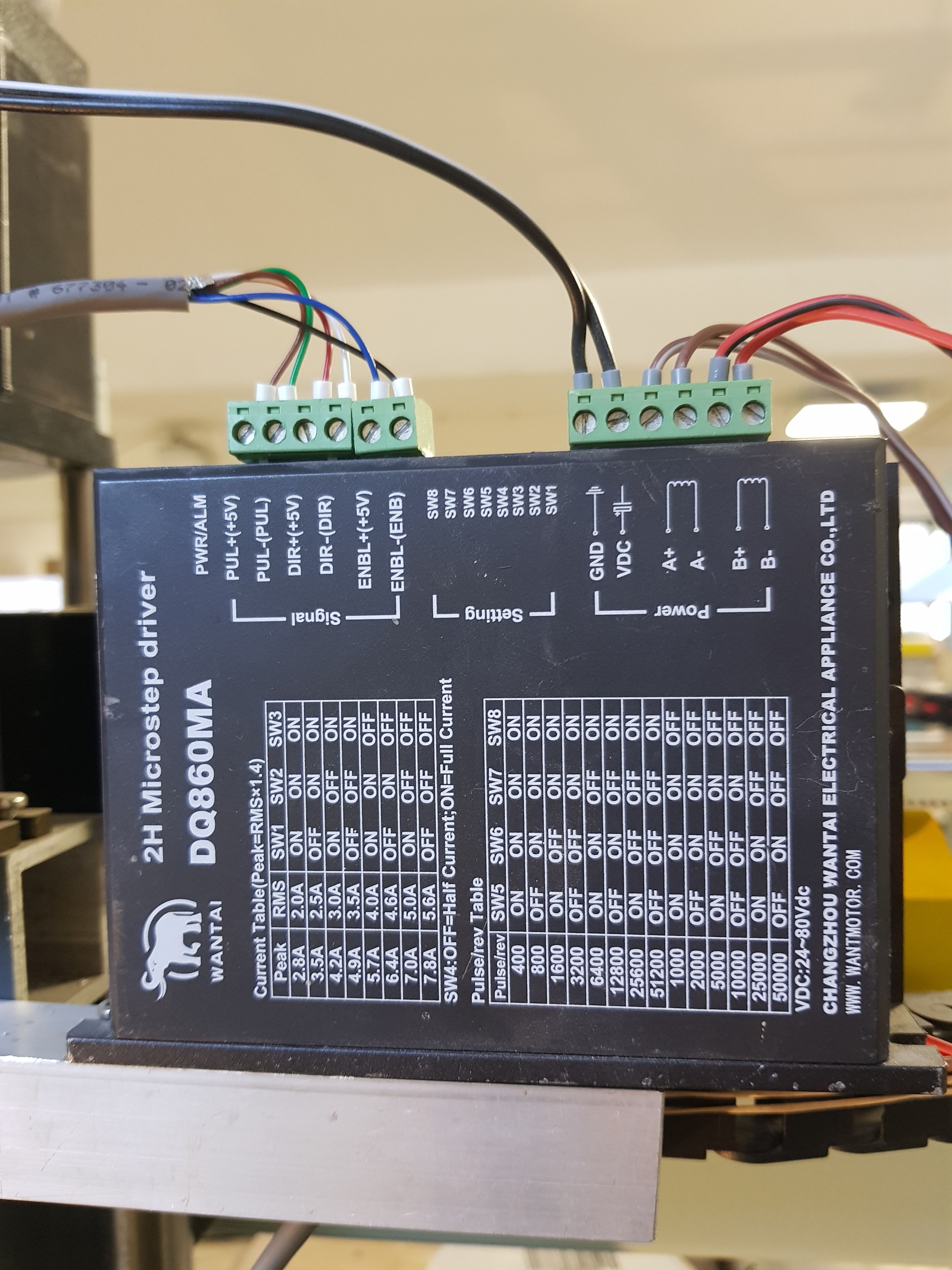
    I am currently building a clay printer with 2 external drivers.
    The drivers are the dq890ma, I have assigned the outputs and I tried some settings in the config. I am using the breakout board for the two drivers.
    when I power the duet the motor is idle and there is no resistance when turning. when I try to move that motor it only clicks once and it has restistance when turning with my hands.

    my config:
    ; Drives
    M569 P0 S1 ; physical drive 0 goes forwards
    M569 P1 S0 ; physical drive 1 goes forwards
    M569 P2 S1 ; physical drive 2 goes forwards
    M569 P3 S0 ; physical drive 3 goes forwards
    M569 P4 S0
    M569 P5 R1 T4:4:4:0
    M569 P6 S1
    M584 X3:4 Y0:1 Z5 E6 ; set drive mapping
    M350 X16 Y16 Z16 E16 I1 ; configure microstepping with interpolation
    M92 X79.74 Y79.74 Z627.45 E480.00 ; set steps per mm
    M566 X900.00 Y900.00 Z12.00 E120.00 ; set maximum instantaneous speed changes (mm/min)
    M203 X500.00 Y500.00 Z20.00 E3000.00 ; set maximum speeds (mm/min)
    M201 X500.00 Y500.00 Z100.00 E200.00 ; set accelerations (mm/s^2)
    M906 X2400 Y2400 Z2400 E2400 I30 ; set motor currents (mA) and motor idle factor in per cent
    M84 S30 ; Set idle timeout

    I hope someone can help me.

    thanks

    1 Reply Last reply Reply Quote 0
    • undefined
      jay_s_uk
      last edited by jay_s_uk 18 Nov 2020, 09:52

      you need to add a timing value to the M569.
      I use the similar drivers (DM860H) on my CNC and have the following for each driver.

      M569 P0 S0 T2.5:2.5:10:5
      

      Owns various duet boards and is the main wiki maintainer for the Teamgloomy LPC/STM32 port of RRF. Assume I'm running whatever the latest beta/stable build is

      1 Reply Last reply Reply Quote 0
      • undefined
        mitchel kraai
        last edited by 18 Nov 2020, 10:07

        I tried that, but it makes no difference.

        1 Reply Last reply Reply Quote 0
        • undefined
          jay_s_uk
          last edited by 18 Nov 2020, 10:12

          What board do you have and where/how do you have them connected?

          Owns various duet boards and is the main wiki maintainer for the Teamgloomy LPC/STM32 port of RRF. Assume I'm running whatever the latest beta/stable build is

          1 Reply Last reply Reply Quote 0
          • undefined
            mitchel kraai
            last edited by 18 Nov 2020, 10:15

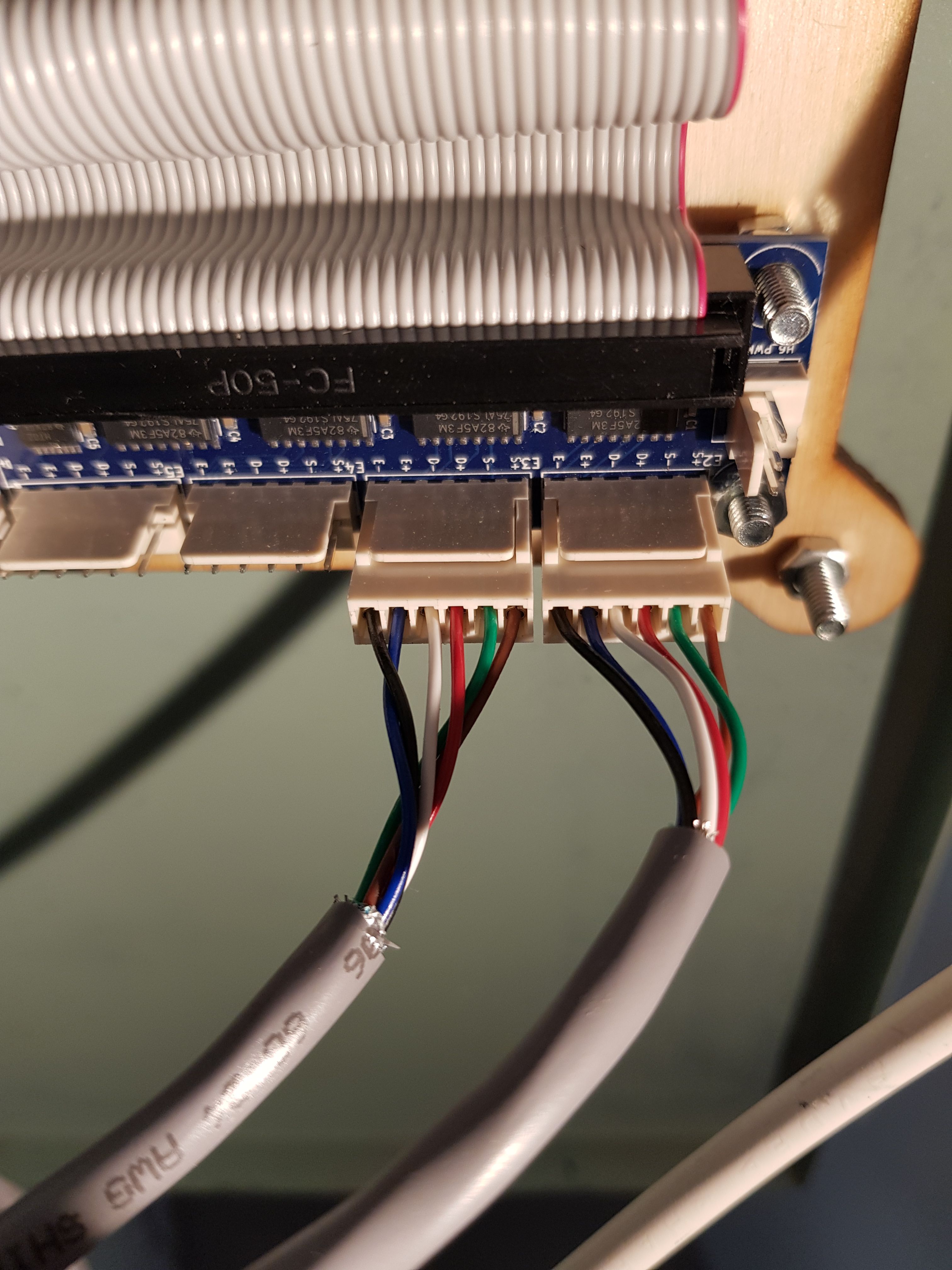
            I have the duet board v1.04. With the breakoutboard.
            I conected all the 6 ports, S+ S- D+ D- E+ E-.

            1 Reply Last reply Reply Quote 0
            • undefined
              jay_s_uk
              last edited by 18 Nov 2020, 10:30

              your driver mapping is incorrect then.
              Please see here https://duet3d.dozuki.com/Wiki/Duet_Expansion_Breakout_Board

              Owns various duet boards and is the main wiki maintainer for the Teamgloomy LPC/STM32 port of RRF. Assume I'm running whatever the latest beta/stable build is

              1 Reply Last reply Reply Quote 0
              • undefined
                mitchel kraai
                last edited by 18 Nov 2020, 10:35

                no I dont think so, my z motor is connected to E2 that is port 5.
                I assigned my Z to 5.
                M569 P5 R1 T2.5:2.5:10:5
                and this is the line for the Z motor.

                1 Reply Last reply Reply Quote 0
                • undefined
                  jay_s_uk
                  last edited by 18 Nov 2020, 11:03

                  is the R value correct?

                  Rnnn Driver enable polarity: 0 = active low, 1 = active high, -1 = driver is always disabled and is not monitored (default 0)
                  

                  Which side of the driver do you have the signal from the board wired to?
                  I have mine wired to the positive side of direction, pulse and enable, with R set to 0.

                  Are you also using M564 H0 or setting G92 Z0 to allow the motor to be moved without homing?

                  Owns various duet boards and is the main wiki maintainer for the Teamgloomy LPC/STM32 port of RRF. Assume I'm running whatever the latest beta/stable build is

                  1 Reply Last reply Reply Quote 0
                  • undefined
                    mitchel kraai
                    last edited by 18 Nov 2020, 11:22

                    I tried R1 and R0, it makes no differense.
                    If I am correct you conected S+ from the break out board to S- on the driver? the same as D and E?

                    yes I have also the M564 H0 in my config

                    1 Reply Last reply Reply Quote 0
                    • undefined
                      jay_s_uk
                      last edited by 18 Nov 2020, 11:30

                      I don't use a breakout board (as I'm running an SKR Pro) but you would typically connect Step+ to Pul+, Dir + to Dir+ and Enable+ to ENA+. The same goes for the negative outputs.

                      Owns various duet boards and is the main wiki maintainer for the Teamgloomy LPC/STM32 port of RRF. Assume I'm running whatever the latest beta/stable build is

                      1 Reply Last reply Reply Quote 0
                      • undefined
                        mitchel kraai
                        last edited by 18 Nov 2020, 11:37

                        oke, how do you have your dip switches on the drivers?
                        and do you have your driver connected to the 5v pin or 3.3v pin?
                        I am thinking of skipping the break out board for testing.

                        1 Reply Last reply Reply Quote 0
                        • undefined
                          jay_s_uk
                          last edited by 18 Nov 2020, 11:43

                          Mine just has dip switches for steps per revolution and driver current.
                          And I run mine off 3.3v. They seem to run fine from that but your experience may vary.

                          There is a note about this on the breakout board page.

                          The Duet Expansion Breakout Board uses a differential output signal of -3.6V to +3.6V. The differential outputs help the LEDs in the optocouplers in most drivers turn off faster. Also they are compatible with drivers that accept RS485 signal levels instead of 5V. Most external drivers are quite happy with the 3.6V differential signals. However, for those few drivers that really do need 5V, you can achieve this by connecting STEP+ from your driver to +5V, which is available on the H6_PWM and/or H7_PWM pin headers (see wiring diagram above), and STEP- for your driver to STEP- on the expansion board. Similarly for DIR and ENA.

                          Owns various duet boards and is the main wiki maintainer for the Teamgloomy LPC/STM32 port of RRF. Assume I'm running whatever the latest beta/stable build is

                          1 Reply Last reply Reply Quote 0
                          • undefined
                            mitchel kraai
                            last edited by 18 Nov 2020, 11:55

                            I tried that also, it makes no difference.
                            currently I am completely stuck...

                            1 Reply Last reply Reply Quote 0
                            • undefined
                              jay_s_uk
                              last edited by 18 Nov 2020, 11:58

                              can you post a photo of your wiring?

                              Owns various duet boards and is the main wiki maintainer for the Teamgloomy LPC/STM32 port of RRF. Assume I'm running whatever the latest beta/stable build is

                              1 Reply Last reply Reply Quote 0
                              • undefined
                                mitchel kraai
                                last edited by 18 Nov 2020, 12:11

                                20201118_130953.jpg 20201118_131014.jpg

                                1 Reply Last reply Reply Quote 0
                                6 out of 15
                                • First post
                                  6/15
                                  Last post
                                Unless otherwise noted, all forum content is licensed under CC-BY-SA