Robotic kinematics
-
The rollers are symmetrical.
-
@roiki11 ok, thank you!
-
I've started to describe my first prototype now, which I call "Type 1" here: https://forum.duet3d.com/topic/20209/robot-type-1-45-cm-belt-gear-direct-drive-r0
The main discussion about gear types, firmware, future direction, status etc. will stay here. -
@JoergS5
Hi! were you able to try the print? -
@tony73 I have some tasks left, but I see the finish line!
The taks left:
- belt tension of big rotation plates is not good enough
- endstops
- calibration of Axis 1 by 3 points
- Axis 1 replace aluminium extrusion through hollow square
- hotend assembly
- better precision of hinges by replacing 8 mm holes by 16 mm F688 ball bearings (currently one arm with 16 mm, one with 8 mm each)
- replace stepper-arm connectors from 2 mm to 4 or 5 mm thick connectors
- wiring and filament routing by hiding in arms
-
@JoergS5
Hello! how is the construction of the robot going? -
I currently improve the build
- combine the balanced arms with the first approach of 4 arm elements for each arm for higher stiffness
- try with wood arms first to avoid waste aluminium material
- axis 1 will get 3 columns, where 2 of them will be able to be changed in height for calibration of print height on the bed
- describe the elements with OpenScad, which has an animation mode also
- the extruder/hotend will be Nema 17 pancake with Bondtech and Volcano hotend. Axis 5 about 800 g, more than calculated.
- maybe I change the arms from 20x10 to 30x10 or 40x10 or 40x20, so wires can be routed inside the arms, and F608 instead of F688 can be used also as an option
-
@JoergS5
Merry Christmas!! how does the modification of the robot proceed? -
@tony73 I wish you a merry christmas too. It's a difficult time, I hope you and all here are well!
I made a pause for a few days, but thinking about how to proceed. I have a good plan how to achieve the goal. I was thinking about the different gears. The belt based gear was a good idea imho, because it's easy to make it. I will proceed on Monday.
After finishing the prototype, I'll develop the firmware for a 6 axis robot with matrix calculations. And a firmware to handle two robots at the same time with collision avoidance.
-
@JoergS5
is everything okay with you? I hope so !! in my family and relatives everything is fine! I wait for your prototype and I agree with you! choosing belts and pulleys is a good idea! The perfect but expensive alternative is with harmonic drive !!! if you do the firmware for the 6-axis robot it will be the maximumof the masterpiece !!!! I discovered something that could be useful, I helped a friend to fix an old VHS video recorder, the rotating head (this in the photo)

it is aluminum, two bearings a steel shaft, the two aluminum cylinders of the head are (similar) to a crossed roller bearing, it is very precise, tested with comparator! ľ steel axle is 6mm, it can carry not very big weight, but it could be used for a robot like your prototype, but smaller size !! too much weight can be a problem !! -
@tony73 thank you, we are well in the family, but some friends and related had the virus. Which remembers us how serious it is!
I will try to build a robot as small as possible as next prototype*), your little precise roller bearing may be useful if you want to rebuild it. I have a VHS recorder also, I'll look into it, this is a good idea. If it can be used, buying some old defect recorders in ebay may be an option. I should look into an LP player also, but I have only an expensive one which I still need. But I have several old harddrives, maybe those have valuable parts too. I wanted to try building a tesla turbine from them (as an experiment), but this is not so important like the robot project. Reusing existing parts was a very good idea from you! I will search what I have... Hard drives rotate with high speed and high precision, they should have good hinges.
*) I'd like to build one for printing 10x10x10 cm objects, placeable everywhere, and nice looking. Light with Bowden hotend.
Developing a multiple 6 axis robot is my goal from the beginning. I described the idea in https://reprap.org/forum/read.php?185,824669 what I want to achieve. A parallel scara, robot, and cantilevered cartesian printer can print from one side, so one can use 4 of them on every side to print at the same time. This would be my goal, together with an additional robot from downside to hold the object (to turn it for overhangs without support material) and with robot from the upside with a camera to control the quality of the print. So 6 robots at the same time. A lot of drivers, a lot to do for the firmware
")
I did not think I could develop firmware for a 6 axis robot, so I started with parallel scara, now 5 axis robot, 6 axis robot comes next, then multiple robots with collision detection.
-
I thought until today that a parallelogram structure with R1 mode would be the best solution. But when arm3 is in line with the vertical arm4 (always when arm 3 is vertical too), the vertical arm4 is very unstable, similar to a singularity:
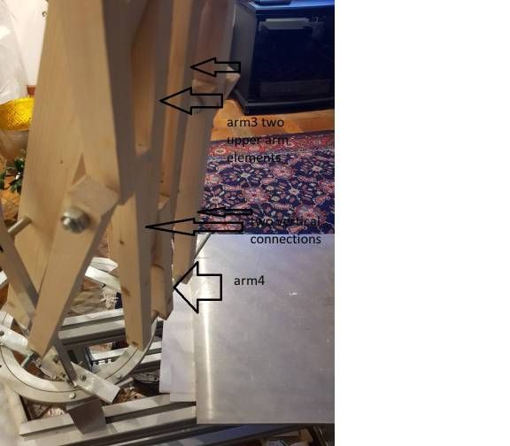
Mathematically arm 4 stays vertical, but every part has a few micrometers play. Arm 4 can rotate some mm because of that.
Unfortunately the regions where arm 3 is vertical is at a lot of places (a cone from bed Z0 towards axis 1 high Z). This limits the precision advantage of R1 mode. I'll concentrate on R0 mode now, with actuator 4 for axis 4.
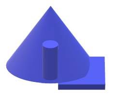
Problematic conic area where arm 4 can rotate with xy inaccuracy (if axis 5 rotates, this area is even bigger):
Kuka KR700 has a different solution for the arm elements which fixes the 4th axis, this may still be an option for a R1 mode. I let R1 remain in the firmware, but will not build robots with R1 mode for some time. This means, Duet 2 and Mini 5+ need an extension board for 6 actuators.
The Type 1 prototype has 8 actuators:
- 5 for the 5 axes
- 1 for extruder
- 2 to calibrate axis 1, standing on 3 columns, 1 of them fixed, 2 of them to be calibrated by actuator with differential screws.
For Type 1, Duet 3 and Mini 5+ are used together with the 3HC board, Mini 5+ using one of 3HC's drivers for the Nema 23 of axis 2 with 3.5 A.
-
This post is deleted! -
This post is deleted! -
This post is deleted! -
This post is deleted! -
This post is deleted! -
This post is deleted! -
@tony73 and all, I will proceed with the robot implementation from March 2nd, with the following priorities:
- finish prototype with an implementation to be able to print
- migrate firmware to
tag 3.2.2 (some libraries 3.2)3.3 - test firmware code
- describe homing and implement the functionality which is described in documentation, but is missing
- describe sample config for Duet 2, Duet 3 and Mini 5+
- try a servo iHSV57 with 1XD card for axis 2, compare precision with stepper solution
- document how to build the prototype
- review print results, gather ideas for improvement, summarize lessons learned
- after that, I start developing the 6 axis robot
If someone has an additional topic for the first steps to proceed, please tell me.
-
@JoergS5
Hi! how are you? About a month ago I bought a used harmonic drive, the 14 - 50 complete with body and cross roller bearing. I found that when it is mounted on a robot, with the engine off, with a large load, the joint can fall, but it is not a problem because the load should be very large !!! the ratio of 14 - 50, that is 1 to 50 creates a very big brake! I tell you this because I did not know that a harmonic drive could rotate with the engine off, I was amazed to see this thing! I'll put you a video link of a guy showing this behavior, on a 3d printed robot! ľ articulation that rotates is a 14 - 50 like mine !!
https://m.youtube.com/watch?v=766F_8LPM9c