Duet 3 Mini 5+ Superpinda output not being recognized
-
Hi everyone,
I am trying to setup a SuperPinda from Prusa with the Mini 5+ for mesh bed leveling and defining the Z offset on a MK3S Bear. It works similar to the normal Pinda that Prusa uses but has built-in temp compensation.
I have configured it like this:

For the connection to the board I used IO_3:
- Output of SuperPinda: io3.in
- GND: GND
- VCC: 5V_EXT
I am doing the static test (https://duet3d.dozuki.com/Wiki/Test_and_calibrate_the_Z_probe#Section_Static_test_using_the_web_interface) and get the value "0" in DWC when the probe is not triggered. It does not change though when the probe is triggered (there is a light on the SuperPinda which turns of when it is being triggered and this works as expected when I hold a metal ruler there).
Is something configured wrong?
Edit: I am on the latest 3.2 releases
-
can you show a picture of your wiring?
-
I happen to have a SuperPINDA on hand that I was getting ready to install myself on my bear so took a few minutes to wire it up and test it out. I hooked it up to a Mini5+ on io3 to be as close to your config as possible.
First thing I thought that the probe was supposed to read zero until it triggers so I changed the line to
M558 P5 C"^io3.in" H5 F120 T6000 ;Removed the !
G31 P500 X23 Y5 Z2.5
Need to double check the ! but it triggers none the less.
Like @Veti said it is worth checking your wiring to make sure it is in the right place.
It should look similar to this
Blue = Ground
Brown = 5V
Black = Signal
-
Thank you both!
After reading you comments, I realized I had an outdated wiring diagram and the "in" and "out" as well as "5V" and "3.3V" are actually the other way around. This is what I had:
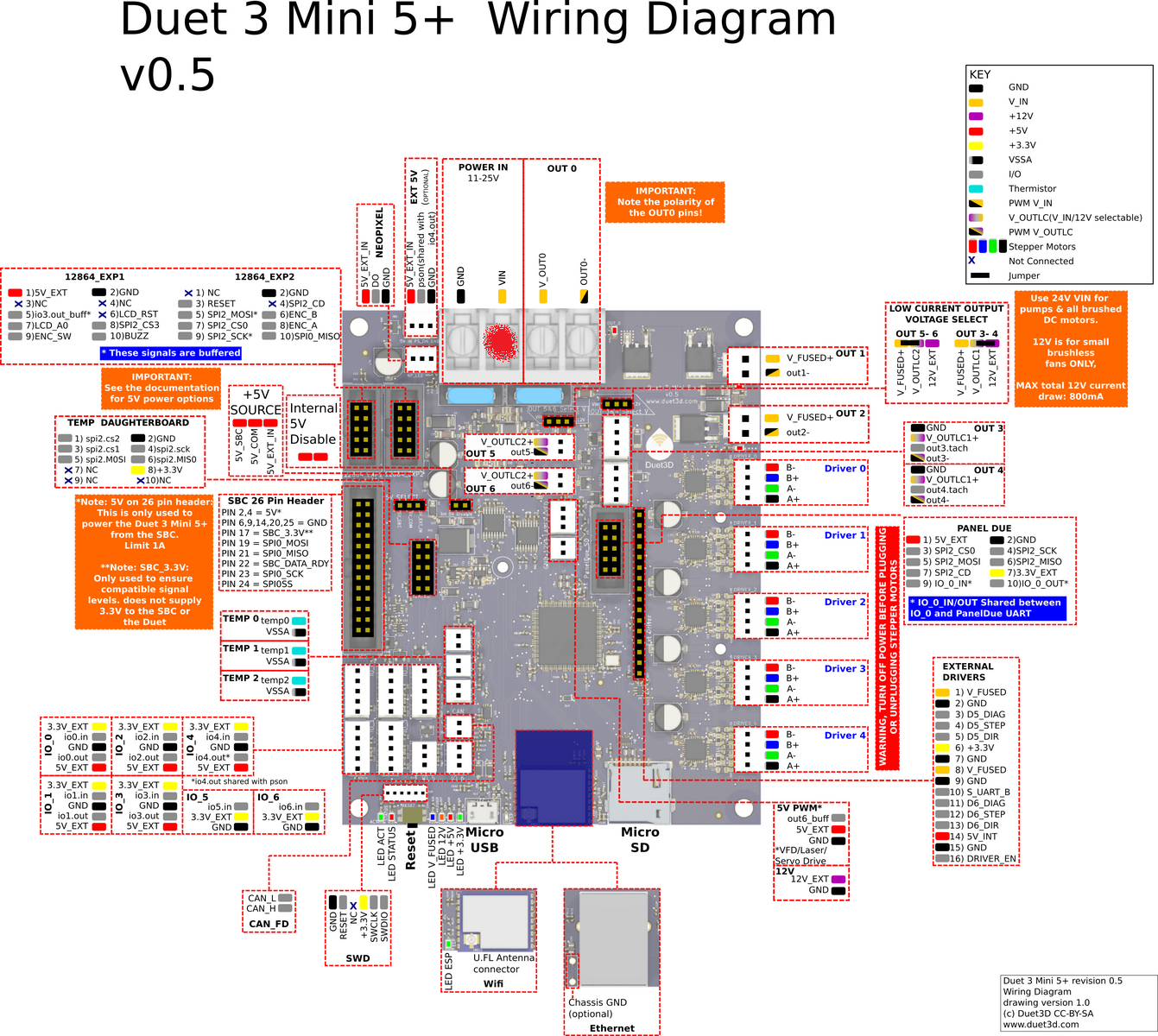
I wired it correctly according to https://duet3d.dozuki.com/Wiki/Duet_3_Mini_5plus_Wiring and now everything works fine.
-
yes the initial diagram was incorrect.