Not homing in correct direction.
-
Ok i will change that.
Does this seem more correct now in my config?
; Z-Probe BLtouch
M950 S0 C"heater3" ;create servo pin 0 for BLTouch
M558 P9 C"^zprobe.in" H5 F200 T6000 ; set Z probe type to bltouch and the dive height + speeds
G31 P500 X0 Y0 Z2 ; set Z probe trigger value, offset and trigger height
M557 X15:215 Y45:195 S20 ; define mesh grid -
Also I was messing around with the mesh settings there on the x andy, im changing them more to the center right now.
Edit i think i just realized thats describing the dimensions of where i can probe.
-
@BattleDroid said in Not homing in correct direction.:
M950 S0 C"heater3" ;create servo pin 0 for BLTouch
Almost. the pin name is
exp.heater3Also don't forget to set the XYZ offset of the probe from the nozzle in G31
G31 P500 X0 Y0 Z2 ; set Z probe trigger value, offset and trigger height
https://duet3d.dozuki.com/Wiki/Test_and_calibrate_the_Z_probe
-
Ok, in relation to that. Do I use how far the probe is from the nozzle? or Nozzle from the probe?
Example: I used
G31 P500 X24.1 Y21.4 Z-4.5 ; set Z probe trigger value, offset and trigger height. The probe being closer to the front of the nozzle(+), and to the right (+).Edit, I just seen the link you added after I replied, reading through that now.
-
Ok reading that, and going back a bit here. Before I can test and calibrate I believe I need to get the probe to retract properly first. I do have both of those macro files in /sys. When I send m401 and m402 nothing seems to happen. Same if I send M280 P0 S10. When I first supply power to the board turning the printer on the probe will deploy and retract twice.
I read through the BLtouch wiki a couple times now, but I believe we covered most of that here already, the labeling for the BLtouch and whatnot. I'm not sure where to look next. Aside from my probe in/out files. Do I need an additional m280 code in the config.g file? -
Hi,
Are you connecting the BLTouch to the 50 pin expansion connector on the Duet 2 or to a Duex 2/5 board?
Frederick
-
@fcwilt
Hello,Yes I do have it connected to the 50 pin expansion. 1) +5v 2)GND 8)Heater3 and then connected to zprobe pins: z probe in and ground. Basically just how the wiki shows. I am using duet 2 board.
-
@BattleDroid said in Not homing in correct direction.:
@fcwilt
Hello,Yes I do have it connected to the 50 pin expansion. 1) +5v 2)GND 8)Heater3 and then connected to zprobe pins: z probe in and ground. Basically just how the wiki shows. I am using duet 2 board.
OK if the probe self tests on power up you've got the +5 and GND connections right.
That leaves the Heater 3 connection - double check just to be sure.
Also try to verify if whatever you are using for an extension cable has continuity from end to end for that connection.
M280 P0 S10 should deploy and M280 P2 S90 should retract.
I believe that M280 P0 S160 initiates self test - you could try that.
Frederick
-
Can you check your firmware version? Send M115
Should be 3.2
Also send M98 p"config.g" and report what it says.
Did you change that pin name to exp.heater3?
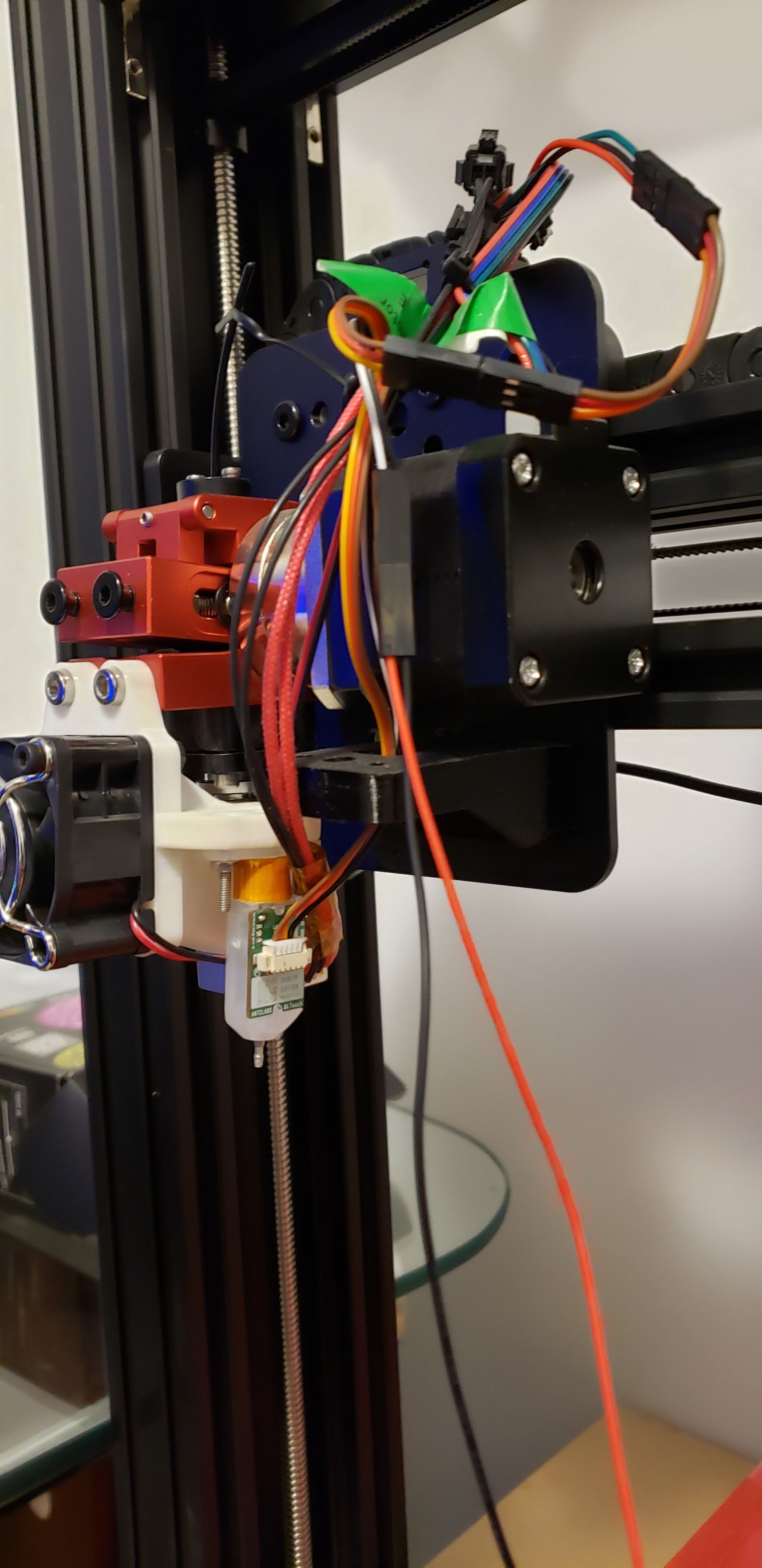
Photo of the wiring?
If you send those m280 commands in the console do they make the pin go in and out?
-
I have tried all 3 of those commands for it not to do anything. Just gives me a good green signal at the bottom. I will double check that connection.
Sending m280 commands also leads to nothing moving, just a green bar with it in console.
I did change that pin name to exp.heater3.FIRMWARE_NAME: RepRapFirmware for Duet 2 WiFi/Ethernet FIRMWARE_VERSION: 3.1.1 ELECTRONICS: Duet WiFi 1.02 or later FIRMWARE_DATE: 2020-05-19b2
M98 p"config.g"
HTTP is enabled on port 80
FTP is disabled
TELNET is disabled
Warning: Heater 0 appears to be over-powered. If left on at full power, its temperature is predicted to reach 365C
Warning: Heater 0 appears to be over-powered. If left on at full power, its temperature is predicted to reach 203CIll try to figure out a photo of the wiring here. Hopefully it works.

-
Check the continuity of that wire. Try connecting the bltouch directly without cable extension.
That's the right pin and the config should work. So check the wires.
-
It looks like you have a metal pin.
I seem to recall that the units with a metal pin required something to be done to make them work on a 3.3 volt signal - I think.
Frederick
-
So after supper here I took the BLtouch off, and plugged the white and black directly to the board, and then I took the extension cable out and am just using the one cable going to 5v, gnd, and heater3. But I noticed now when I power on the board now. It still probes in and out. But now the red light on the BLtouch is blinking? M401/402 still doesnt work. Does this mean it could be a wiring issue? Also I don't know if it matters but I just have it sitting on the control box upside down since the white and black are pretty short.
To edit what I just typed. Instead of erasing, so you can see whats going on. I turned power off. Just rotated the bl touch to point down. Turned power back on. It did its probe thing. I entered 401 and it probed out. And m402 probed in. Glad to see it working. So initially it must be a wiring thing like you guys mentioned. But I also ask for the sake of it could the orientation of the bltouch have anything to do with the blinking or what not? Having it upside down?
-
Yeah the bltouch needs to be upright to work properly. Upside down won't let the pin drop and it will error and flash. But at least you've confirmed it works when directly connected. So wiring is the issue.
-
Gotcha! Well as of right now I had rewired all the wires on the BLtouch. And all seems to be working well! It ended up being the 3 wire cable going to power ground and heater 3. I can now home everything correctly. And all seems to be working thus far. Just working on tuning nozzle height and position with the BLtouch a bit closer. And then I'm going to try to heat up the nozzle and try kicking out some filament before I start calibrating the extruder and making sure everything is dialed in correctly.
Thank you guys for your help. I would not have figured it out without. Very much appreciated.
-
Hey guys, had a simple question about wiring cooling fans to the duet. Pretty basic but I cant find a definite answer and just want to be sure before I go ahead. Instead of making a new thread ill just post here.
I have printed some things for my widow. I'm looking to hook up a couple print cooling fans. I cant find an explanation on how to wire it up. I don't get the whole, 5v, VIN?, and external. I understand external being the power supply. Which is 24v. And 5v is basic 5v. I cant seem to find an answer from the wiki or the forum what vin is. Is it as simple as plug and play and then change some config files? I have two fans I'd like to hook up, and then get going. Which are both 24v. But I don't want to just hook them up and have something not right and short the board. Also I cant tell if they are pwm or not, or if you can even get 24v pwm. That's another thing I cant figure out. Its easy to find 12v everything, but 24v seems harder to sort through. I guess you can say I'm hesitant until I can find a proper answer. Possibly overthinking it. Thanks again.
-
Hi,
I am a bit confused.
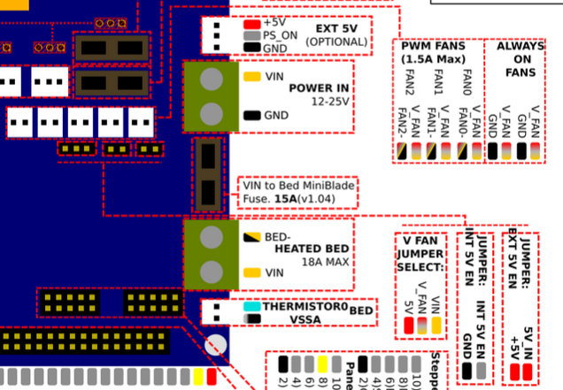
The Duet 2 WiFi has connections for 5 fans.
Two are always on - if the board has power the fans run.
Three are variable speed using pulse width modulation.
There is a jumper that determines if the power supplied to the fans via the V_FAN pins on the fan connectors is 5V or VIN - which I gather for your setup is 24V.
The FAN0, FAN2 and FAN2 pins on the fan connectors are switched to GND by MOSFETs.
When the MOSFET is conducting one side of the fan is connected to GND, the outer side to V_FAN.
When that condition exists the fan runs.
When the MOSFET is NOT conducting one side of the fan is NOT connected to GND, the outer side is still connected to V_FAN.
When that condition exists the fan does NOT run.
What things don't you understand?
Frederick
-
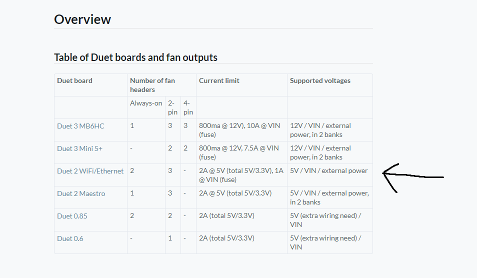
I think you summed it up pretty well for me actually. Sorry if I was confusing. I was getting wound up in the supplied voltages. And using the jumper pins. I think I was over thinking it. I couldn't figure out in my head what vin was, but after you wrote it out I think I got it. And seems clear. Its either 5v or vin(24v). I got caught up in the "supported voltages (5V / VIN / external power, in 2 banks)". For some reason I was thrown off about it. But now I realize the external power, in 2 banks is the always on fans. As long as I have the jumper set to vin I should be alright to hook up 24v fans in the pwm slots. Thank you for clearing that up for me, I feel dumb asking that now. Even re reading the wiki makes more sense to me now.
-
@BattleDroid said in Not homing in correct direction.:
I got caught up in the "supported voltages (5V / VIN / external power, in 2 banks)". For some reason I was thrown off about it.
I don't understand what you are talking about.
But now I realize the external power, in 2 banks is the always on fans.
Why do you think that?
Notice that for ALL five fan connectors one pin is labeled V_FAN.
Notice that the V FAN jumper selects between 5V and VIN feeding power to V_FAN.
Perhaps you are confused by the two jumpers that control the source of the 5V for the board?
-
Well this is why I asked cause I did't understand I guess. And I could have been getting confused between those. But realistically I guess I just didn't understand that part of the board. But I believe I understand now for the most part. So the jumper can either be 5v/ V_fan supplied by the board. Or V_fan/VIN which would be 24v supplied for the power supply. As for the other jumpers, I still don't quite understand. But I assume they are irrelevant since I'm getting power through VIN and not 5v?
Also sorry I also wasn't too clear earlier too. I was referencing the duet wiki. Jumping back and forth between the wiki, and the diagram of the board. I also realize i quoted the line under it which added the two banks part. But still basically gives the same information.
This is why I thought the two always on fans would be different (external power), and the other three would be determined from the jumper. But I was mistaken.
I just want to make sure I properly supply them with 24v and have everything hooked up correctly is all. Just trying to learn it and figure it out best I can. Without messing stuff up. Some things I can be a little slow to learn, others I catch on right away. This I seemed to reread over and just not grasp it.