What setting/s cause this?
-
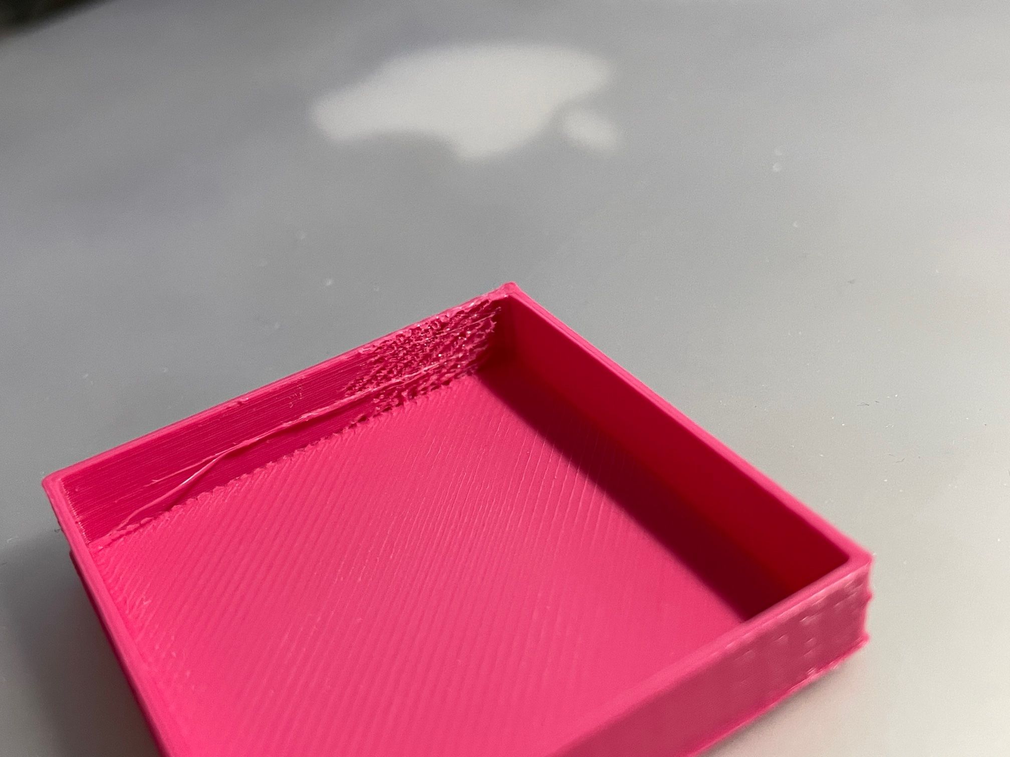
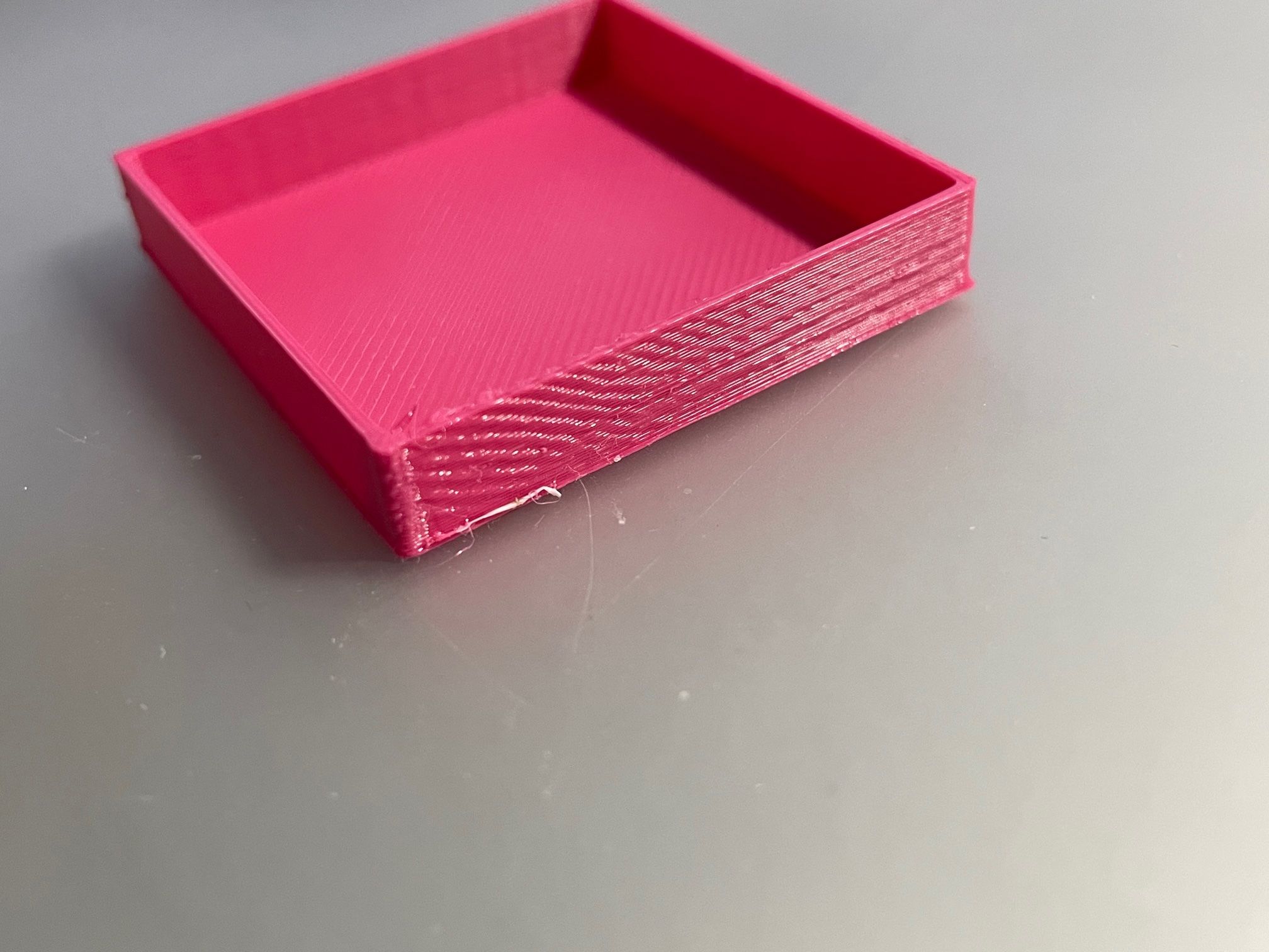
I'm tuning my printer. Things are going okay but I get this stretched effect at the start of a layer. It's visible on the surface of a part. Additional walls may hide it I guess?
Is this linked to acceleration settings, retraction & could pressure advance help?
Thanks.


-
yes that can be caused by retraction.
it could be to much retraction. or the filament slipping.
it could also be a wrong thermistor setting.
post your config.g
-
; Configuration file for Duet Maestro (firmware version 3) ; executed by the firmware on start-up ; ; generated by RepRapFirmware Configuration Tool v3.2.1 on Sat Jan 09 2021 18:02:08 GMT+0000 (Greenwich Mean Time) ; General preferences G90 ; send absolute coordinates... M83 ; ...but relative extruder moves M550 P"ST3Di280 Duet" ; set printer name ; Network M552 P192.168.0.60 S1 ; enable network and acquire dynamic address via DHCP M586 P0 S1 ; enable HTTP M586 P1 S0 ; disable FTP M586 P2 S0 ; disable Telnet ; Drives M569 P0 S1 ; physical drive 0 goes forwards M569 P1 S0 ; physical drive 1 goes backwards M569 P2 S1 ; physical drive 2 goes forwards M569 P3 S0 ; physical drive 3 goes backwards M569 P4 S1 ; physical drive 4 goes forwards M584 X0 Y1 Z2 E3:4 ; set drive mapping M350 X16 Y16 Z16 E16:16 I1 ; configure microstepping with interpolation M92 X91.13 Y106.84 Z1242.228 E104.76:104.76 ; set steps per mm M566 X1600.00 Y1600.00 Z60.00 E120.00:120.00 ; set maximum instantaneous speed changes (mm/min) M203 X6000.00 Y6000.00 Z180.00 E1200.00:1200.00 ; set maximum speeds (mm/min) M201 X500.00 Y500.00 Z20.00 E250.00:250.00 ; set accelerations (mm/s^2) M906 X800 Y800 Z800 E600:600 I30 ; set motor currents (mA) and motor idle factor in per cent M84 S30 ; Set idle timeout ; Axis Limits M208 X-140 Y-75 Z0 S1 ; set axis minima M208 X165 Y75 Z150 S0 ; set axis maxima ; Endstops M574 X1 S1 P"xstop" ; configure active-high endstop for low end on X via pin xstop M574 Y1 S1 P"ystop" ; configure active-high endstop for low end on Y via pin ystop M574 Z1 S2 ; configure Z-probe endstop for low end on Z ; Z-Probe ;M574 Z1 S1 ; Set endstops controlled by probe M950 S0 C"^zprobe.mod" ; create servo pin 0 for BLTouch M558 P8 C"^zprobe.in" H3 F900 T6000 ; Set Z probe type to switch and the dive height + speeds G31 P50 X-43 Y5 Z1.816 ;Set Z probe trigger value, offset and trigger height 1.81 M557 X-120:120 Y-65:75 S15 ; define mesh grid ; Heaters M308 S0 P"bedtemp" Y"thermistor" A"Bed Heater" T100000 B3950 ; configure sensor 0 as thermistor on pin bedtemp M950 H0 C"bedheat" T0 ; create bed heater output on bedheat and map it to sensor 0 M307 H0 B0 S1.00 ; disable bang-bang mode for the bed heater and set PWM limit M140 H0 ; map heated bed to heater 0 M143 H0 S120 ; set temperature limit for heater 0 to 120C M308 S1 P"e0temp" Y"thermistor" A"Left Extruder" T100000 B3950 ; configure sensor 1 as thermistor on pin e0temp M950 H1 C"e0heat" T1 ; create nozzle heater output on e0heat and map it to sensor 1 M307 H1 B0 S1.00 ; disable bang-bang mode for heater and set PWM limit M143 H1 S280 ; set temperature limit for heater 1 to 280C M308 S2 P"e1temp" Y"thermistor" A"Right Extruder" T100000 B3950 ; configure sensor 2 as thermistor on pin e1temp M950 H2 C"e1heat" T2 ; create nozzle heater output on e1heat and map it to sensor 2 M307 H2 B0 S1.00 ; disable bang-bang mode for heater and set PWM limit M143 H2 S280 ; set temperature limit for heater 2 to 280C ; Fans M950 F0 C"fan0" Q500 ; create fan 0 on pin fan0 and set its frequency M106 P0 S0 H-1 ; set fan 0 value. Thermostatic control is turned off M950 F1 C"fan1" Q500 ; create fan 1 on pin fan1 and set its frequency M106 P1 S1 H1:2 T45 ; set fan 1 value. Thermostatic control is turned on ; Tools M563 P0 S"Left" D0 H1 F0 ; define tool 0 G10 P0 X14.275 Y-0.25 Z0 ; set tool 0 axis offsets G10 P0 R0 S0 ; set initial tool 0 active and standby temperatures to 0C M563 P1 S"Right" D1 H2 F0 ; define tool 1 G10 P1 X-14.275 Y0 Z0 ; set tool 1 axis offsets G10 P1 R0 S0 ; set initial tool 1 active and standby temperatures to 0C ; Custom settings are not defined M575 P1 S1 B57600 ;PanelDue interface M912 P0 S1 M501 M911 S21 R23 P"M913 X0 Y0 G91 M83 G1 Z3 E-5 F1000" ; set voltage thresholds and actions to run on power loss -
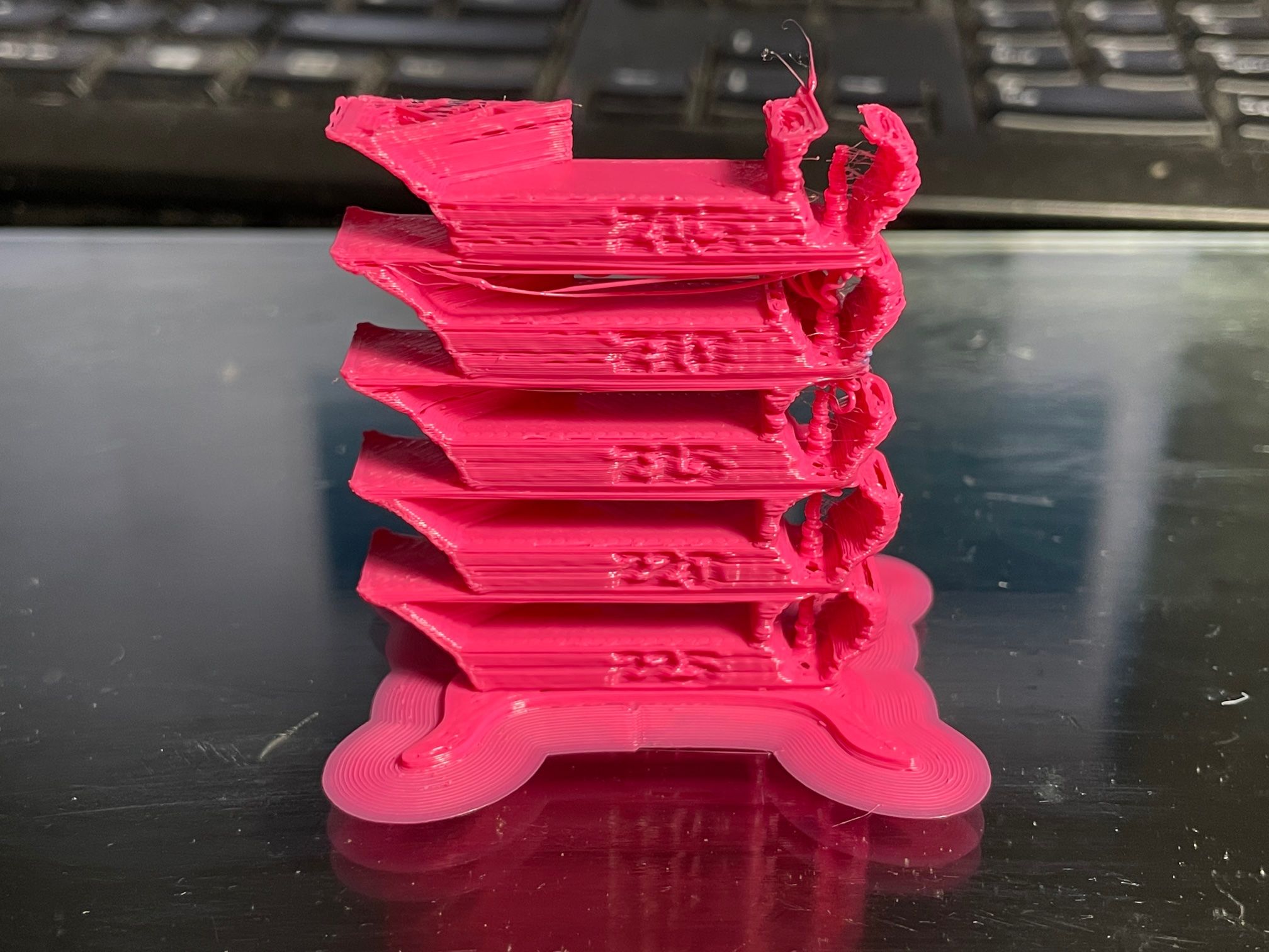
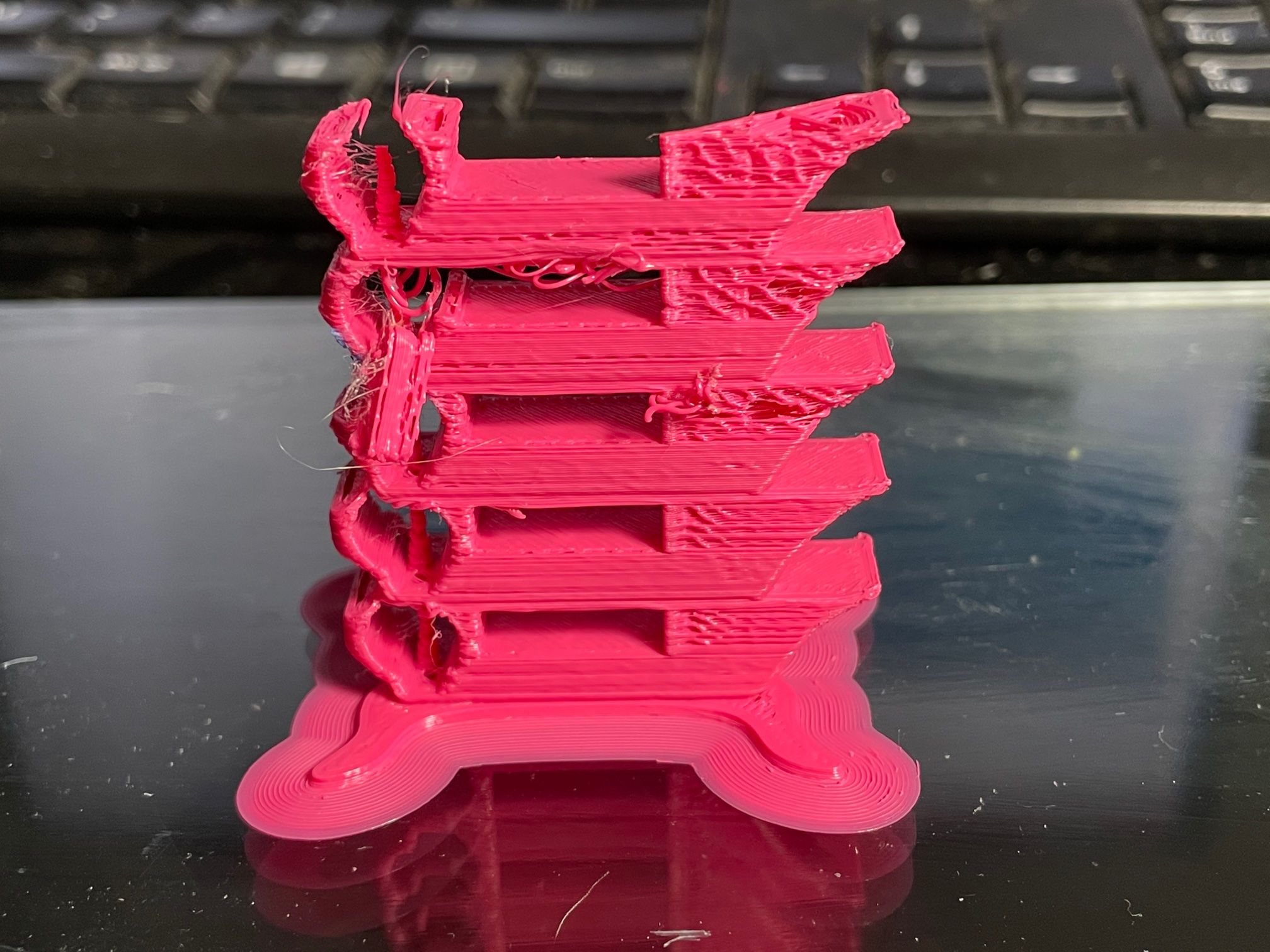
print a temperature tower to see if your thermistor settings is correct.
-
Okay, Will do
-
None of them look great, hotter the better though it seems although I cannot be sure the actual temp correlates with the temp in DWC.
FYI the PLA was only opened at the weekend although I've had it sat around for a while. On my other printer 215 is about the sweet spot for this PLA.


-
@Blacksheep99 said in What setting/s cause this?:
On my other printer 215 is about the sweet spot for this PLA.
if your thermistor setting is incorrect then 215 will not be real 215
it can easily be off by 20-40c -
@Veti said in What setting/s cause this?:
@Blacksheep99 said in What setting/s cause this?:
On my other printer 215 is about the sweet spot for this PLA.
if your thermistor setting is incorrect then 215 will not be real 215
it can easily be off by 20-40cThe other printer is a stock Polaroid 250s so I am assuming it’s calibrated somewhat? That’s my comparison. Point taken though
-
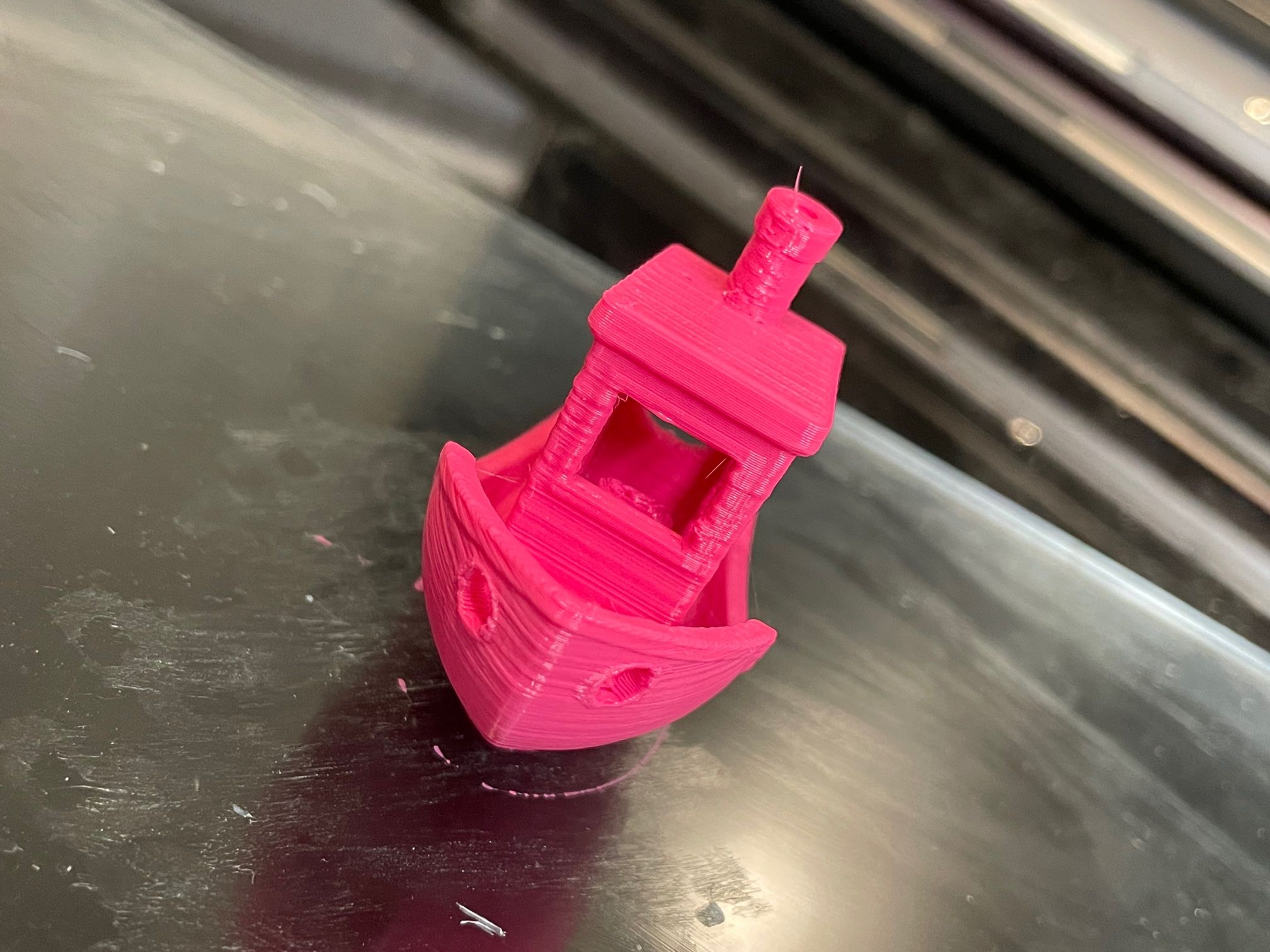
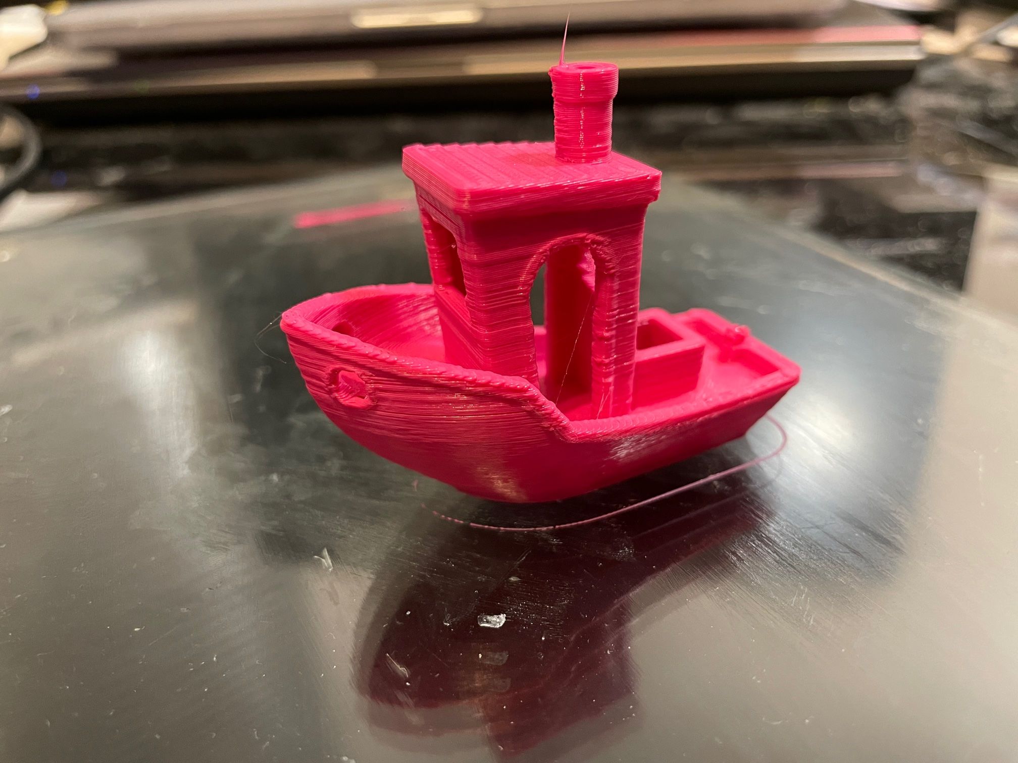
Benchy using my current settings, sliced in Cura 4.8.
0.2layers. Printed at '235' which is too hot for PLA.


-
can you print this
https://www.thingiverse.com/thing:2080224
and try and calibrate your retraction with it.
-
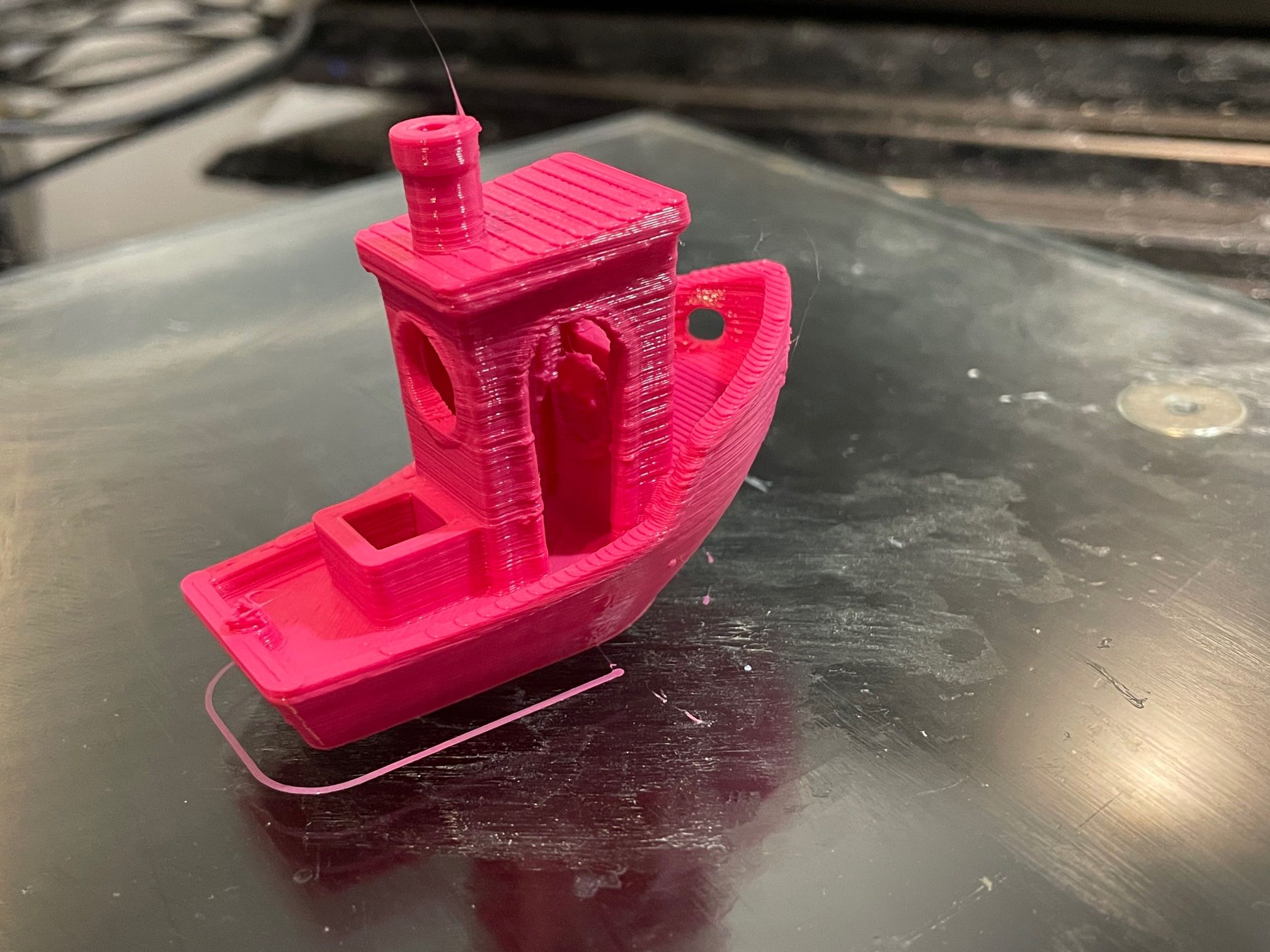
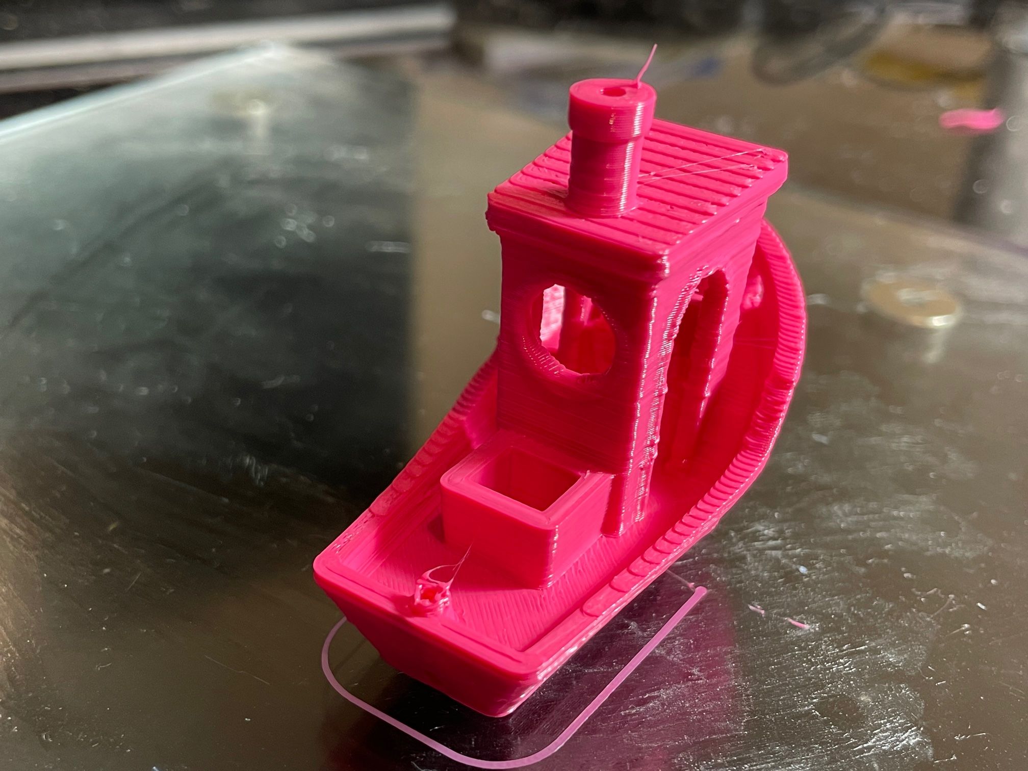
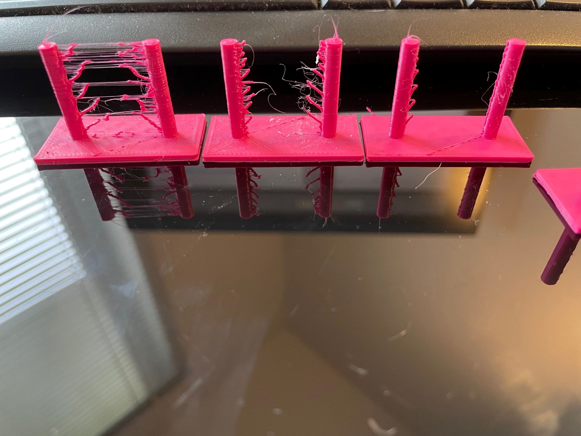
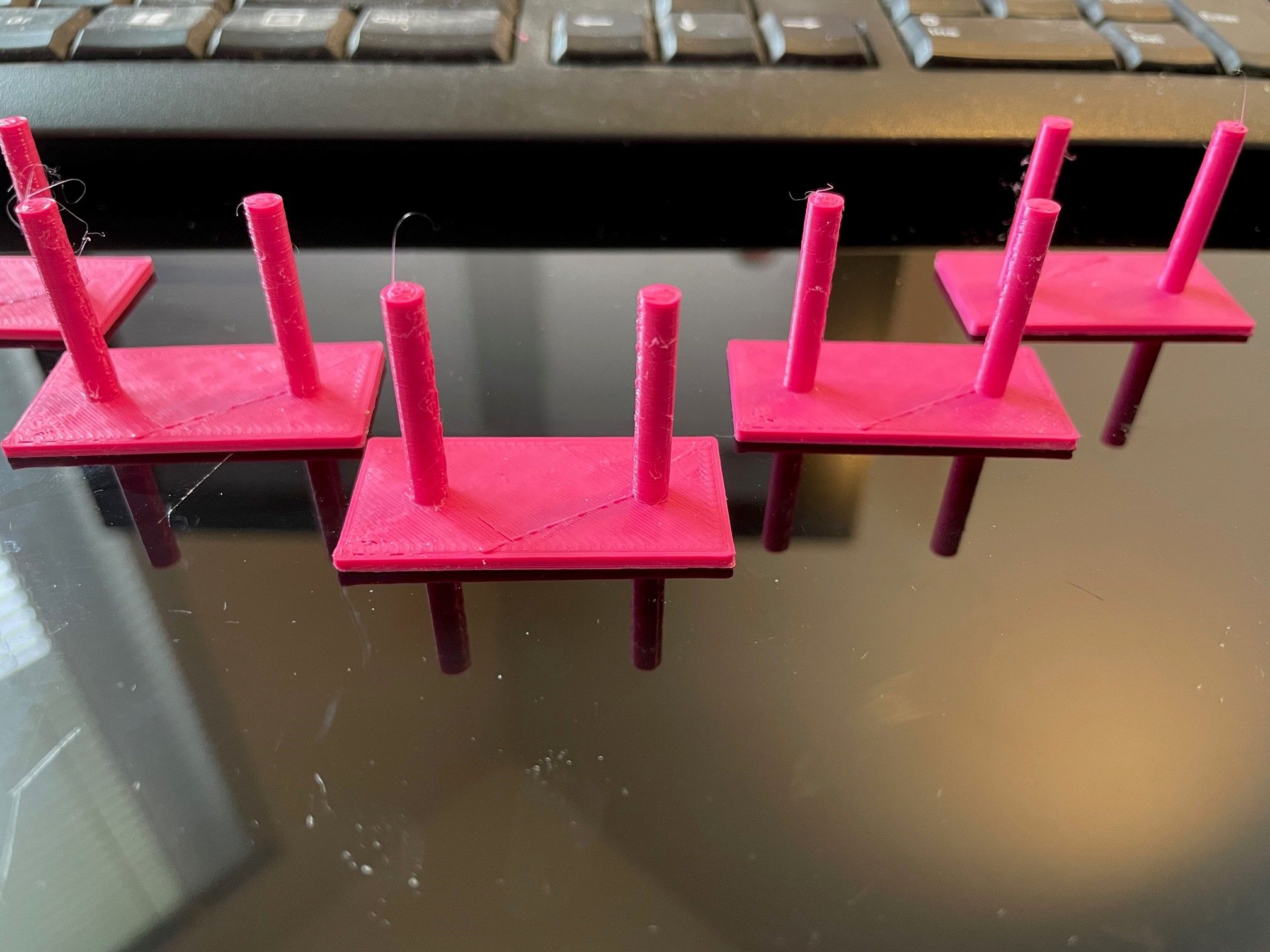
I think 1.6mm retraction 50mm/s looks best.

0, 0.5, 1 retraction

1.5, 1.6, 1.75, 2
I think 1.5mm is close but has some slight surface blobs.
I previously had it set at 2.5mm.
Note: Pressure advance disabled in config.g for these prints.
-
ok see if that improves the benchy. nearly 1cm difference for retraction is a lot.