Stepper definition Z motors
-
@ahwitmer Did you fix the M584?
M584 X2.1:3.1 Y2.0:3.0 Z0.0:0.1:0.2:0.5 U3.1 V3.0 E1.2:1.1:1.0:2.2:3.2:0.3:0.4 P5
Or is that intentional?
Frederick
-
@fcwilt
No that is indeed intentional. It is a double gantry CoreXY. This means that X and U as well as Y and V move in the same direction when printing.Harald
-
@Veti @fcwilt
Veti it is a double gantry CoreXYUV
It is the intention to move the pairs X/U and Y/V simultaneously for now,How do you mean Z does not allow for multiple values?
Do I understand correctly that I have to remove the multiple Z values for the commands M92, M566, M203, M201 and M906 ? Even when they are connected to their own drivers ?Indeed you are right, just tested it, after removing the extraneous data at the Z-steppers do correctly show the correct amperage.
Part 1 solved

The extruders are not yet recognised.
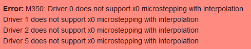
Also get errors on microstepping
Thanks so far!
CoreXYUV
-
Hi,
From the DWC console execute M350 by itself.
If that doesn't reveal the problem try commenting out the M350 in config.g and re-boot.
Then from the DWC console execute M350 with one drive at a time to see if you can find what is causing the error.
My printer is a Cartesian with these commands:
- M584 X0 Y1:2 Z5 E3
- M350 X16 Y16 Z16 E16 I1If I enter M350 X0 I get a driver 0 error.
If I enter M350 Y0 I get a driver 1 error and a driver 2 error.
if I enter M350 Z0 I get a driver 5 error.
All those driver numbers in the errors match with the driver numbers in M584.
Also check config-override.g for a M350 command.
Frederick
-
@fcwilt
Your advice works out. It had to do with the Z parameters. I was using Z:16:16:16:16
After changing it to Z:16, the error message is not shown anymore!My Extruder steppers still do not shown amperage yet.

Harald
-
@fcwilt said in Stepper definition Z motors:
Your M906 has semi-colon where it should be a colon. That of course means everything after the semi-colon is considered a comment.
M906 X3200 Y3200 Z2240:2240:2240:2240 U3200 V3200 E1360:1360:1360 ; 1360:1360:1360:1360 I30
Frederick
-
@ahwitmer said in Stepper definition Z motors:
How do you mean Z does not allow for multiple values?
Z0.0:0.1:0.2:0.5
this is not allowed. z only take 1 values for all
this applies to M92 M566 M203 M201 M906
-
@Veti Indeed, followed up your advise and that works out fine. Thanks!
And the story continues:
My set-up
Mainboard 4 z-steppers (Nema 23, 2.8 Ampere)
Expboard 0: 3 extruders
Expboard 1: X and Y stepper (nema 23, 4 Ampere)
Exp board2: U and V stepper (Nema 23, 4 ampere)Mainboard: 12 V supply
Expansion boards: 24 V supplySwitch to 24 Volt was done in a later moment after I purchased several 12 Volt other elements. Have insufficient space to install another 24V power supply.
Commissioning
Okay now my Z-steppers provide the correct amperage when issuing M906.
Commissioning the Z motors is done by first disabling the endstop requirement by
M564 S0 H0
Pushing the buttons on the machine movement tab should move the motors.Result
Out of the 4, only two Z-steppers react on the commands to move.Both motors move irregularly.
For one of the motors, once it starts stepping it will continue stepping, but it decides itself if it takes the required direction, sometimes it is up, some times it is down or it just stutters at the down command.
The other motor hardly turns and also changes its mind regularly to up or down stuttering.
In addition, the first motor is not activated after the step-cycle is finished, that is okay.
The second motor however remains kept energized. I did not realize it until I found that the motor got quite hot and even the power cable became warm.I have a continuous readout of voltage (both 12 V and 24V) and that one is keeping stable during this excercize.
Changing the mainboard from 12 V to 24 V will likely change the issue of the warm cable. Nevertheless keeping it energised is never the intention. I have to reset the board to get it de-energised.
What would be the reason behind iregular stepping?
Why is one motor kept energised?PS I did not yet switch cables to find out if the cables are crimped (in)correctly.
Harald
CoreXYUV
-
Hi,
If it were me I would comment out the existing stepper configuration commands (M92 M203 M201 M566 M906 M350) and create a test set for one Z stepper at a time.
Then I would verify that each one works on it's on - thus checking the stepper, the wiring and the power).
Divide and Conquer.
Frederick
-
@ahwitmer said in Stepper definition Z motors:
What would be the reason behind iregular stepping?
Why is one motor kept energised?
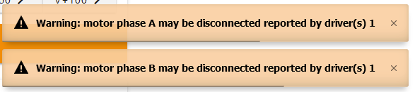
PS I did not yet switch cables to find out if the cables are crimped (in)correctly.Definitely check your wiring and ensure you have the motor phases correctly paired.
-
The pairing of phases is verified again and shown to be connected correctly for all motors connected to the mainboard.
Still the steppers sometimes go up and sometimes go down.Only wondering if there is a difference between
A1 A2 B1 B2 and A2 A1 B1 B2
-
@ahwitmer said in Stepper definition Z motors:
The pairing of phases is verified again and shown to be connected correctly for all motors connected to the mainboard.
Still the steppers sometimes go up and sometimes go down.There appears to be a timing problem related to the expansion boards that deals with this issue.
https://forum.duet3d.com/topic/21326/just-another-bug-with-3hc
Frederick
-
@fcwilt I'm going to take a look at it, thank you..... I'll be back
")
-
@fcwilt @Phaedrux @Veti
Have been busy for some time with other pressing issues.Last weekend I adopted the advise of fcwilt I modified the Config.g file using only one Z-motor (on mainboard driver 0). Then using an extra motor I tried to get it stepping.
It turned out that the cabling and crimping was the main origin of the problems.One cable had to high AWG. That made the stepper squeek and respond differently on commands and got it quite warm.
I checked, recrimped all wires, now I have 4 working cables for the steppers.
Next I tested every driver connection to the mainboard.Now I have three drivers working however the last one (driver 1 on mainboard) did not react to any stepping request. When requesting a large step, the system returns an error message.
Exchanging the cables did not have any effect. The cables are now working like a charm except on driver 1.
I have been careful with the motors not to rotate them when connected to the board.
This has all been done on 3.2. After my finding I decided to install 3.2.2 for the mainboard and the expansion boards. But helas no improvement. The other drivers still perform correctly. Driver 0.1 keeps on having issues....
Did I fry my driver in some way?
-
@ahwitmer said in Stepper definition Z motors:
Did I fry my driver in some way?
Anything is possible, but let's eliminate cabling first since that's the most likely issue. Is there anything visibly different about that driver header? Is the crimp making good contact?
-
@Phaedrux
I have 4 cables for the 4 motors,
I'm using driver 0.0 0.1 0.2 and 0.5
Modified my config.g so that I test driver by driver with any of the 4 cables
In total I test 16 times with a stepper. Every driver with any of the 4 cables.Testing all cables on 0.0 0.2 and 0.5 and rotating/testing all 4 cables work perfectly in
Connecting any of the 4 cables to 0.1 results in the same error as shown above.Because of this I conclude the cables are okay.
The connector on the motherboard looks very similar to the other connectors.
Nothing special there. -
Thanks for the clarity on your testing. Before we conclude the driver is failed, can you share your current config.g? Just in case.
-
@Phaedrux This is my Config file
</>; generated by RepRapFirmware Configuration Tool v3.1.4 on Mon Oct 19 2020 10:28:42 GMT+0200 (Central European Summer Time) ; modified 25 jan 2021 ; General preferences G90 ; send absolute coordinates... M83 ; ...but relative extruder moves M550 P"duet3" ; set printer name M669 K1 ; select CoreXY mode G21 ; in milimeters ; Communication ;M540 Mac Address ; Mac address ;M552 P192.168.0.5 ; IP address ;M554 P192.168.1.1 ; Gateway ;M553 P255.255.255.0 ; Netmask ;M552 S1 ; Drives M569 P2.1 S1 ; X physical drive 2.1 goes forwards M569 P2.0 S1 ; Y physical drive 2.0 goes forwards M569 P0.1 S1 ; Z1 physical drive 0.0 goes forwards ;M569 P0.1 S1 ; Z2 physical drive 0.1 goes forwards ;M569 P0.2 S1 ; Z3 physical drive 0.2 goes forwards ;M569 P0.5 S1 ; Z4 physical drive 0.5 goes forwards M569 P3.1 S1 ; U physical drive 3.1 goes forwards M569 P3.0 S1 ; V physical drive 3.0 goes forwards M569 P0.3 S1 ; Kext1 physical drive 0.3 goes forwards M569 P0.4 S1 ; Kext2 physical drive 0.4 goes forwards M569 P2.2 S1 ; Kext3 physical drive 2.2 goes forwards M569 P3.2 S1 ; Kext4 physical drive 3.2 goes forwards M569 P1.0 S1 ; DEXT3 physical drive 1.0 goes forwards M569 P1.1 S1 ; DEXT2 physical drive 1.1 goes forwards M569 P1.2 S1 ; DEXT1 physical drive 1.2 goes forwards ;M584 X2.1:3.1 Y2.0:3.0 Z0.0:0.1:0.2:0.5 U3.1 V3.0 E1.2:1.1:1.0:2.2:3.2:0.3:0.4 P5 M584 X2.1:3.1 Y2.0:3.0 Z0.1 U3.1 V3.0 E1.2:1.1:1.0:2.2:3.2:0.3:0.4 P5 M671 X0:0:255:255 Y-104.55:115.45:115.45:-104.55 ; Coordinates of probing points M350 X16 Y16 Z16 U16 V16 E16:16:16:16:16:16:16 I1 ; configure microstepping with interpolation M92 X80.00 Y80.00 Z4000.00 U80.00 V80.00 E420.00:420.00:420.00:420.00:420.00:420.00:420.00 ; set steps per mm M566 X900.00 Y900.00 Z12.00 U900.00 V900.00 E120.00:120.00:120.00:120.00:120.00:120.00:120.00 ; set maximum instantaneous speed changes (mm/min) M203 X6000.00 Y6000.00 Z180.00 U6000.00 V6000.00 E1200.00:1200.00:1200.00:1200.00:1200.00:1200.00:1200.00 ; set maximum speeds (mm/min) M201 X500.00 Y500.00 Z20.00 U500.00 V500.00 E250.00:250.00:250.00:250.00:250.00:250.00:250.00 ; set accelerations (mm/s^2) M906 X3200 Y3200 Z2240 U3200 V3200 E1360:1360:1360;1360:1360:1360:1360 I30 ; set motor currents (mA) and motor idle factor in per cent M84 S30 ; Set idle timeout ; Axis Limits M208 X0 Y0 Z0 S1 ; set axis minima M208 X255 Y222 Z340 U255 V222 S0 ; set axis maxima ; Endstops ;M574 X1 S1 P"2.io1.in" ; Expansion board 2, io1.in - active high endstop M574 X2 S1 P"2.io1.in" ; active low endstop ;M574 Y1 S1 P"2.io0.in" ; Expansion board 2, io0.in - active high endstop M574 Y2 S1 P"2.io0.in" ; active low endstop ;M574 U1 S1 P"3.io1.in" ; Expansion board 3, io1.in - active high endstop M574 U2 S1 P"3.io1.in" ; active low endstop ;M574 V1 S1 P"3.io0.in" ; Expansion board 3, io0.in- active high endstop M574 V2 S1 P"3.io0.in" ; active low endstop M574 Z1 S2 ; configure Z-probe endstop for low end on Z ; Z-Probe M950 S0 C"io7.out" ; create servo pin 0 for BLTouch M558 P9 C"^io7.in" H5 F120 T6000 ; set Z probe type to bltouch and the dive height + speeds G31 P500 X0 Y-104.55 Z0 ; set Z probe trigger value, offset and trigger height M557 X0:255 Y0:222 S20 ; define mesh grid ; M671 verplaatst naar bed ; Heaters M308 S0 P"temp0" Y"thermistor" T100000 B4138 ; configure sensor 0 as thermistor on pin temp0 M950 H0 C"out0" T0 ; create bed heater output on out0 and map it to sensor 0 M307 H0 B1 S1.00 ; enable bang-bang mode for the bed heater and set PWM limit M140 H0 ; map heated bed to heater 0 M143 H0 S120 ; set temperature limit for heater 0 to 120C M308 S1 P"temp1" Y"thermistor" T100000 B4138 ; configure sensor 1 as thermistor on pin temp1 M950 H1 C"out1" T1 ; create nozzle heater output on out1 and map it to sensor 1 M307 H1 B0 S1.00 ; disable bang-bang mode for heater and set PWM limit M308 S2 P"temp2" Y"thermistor" T100000 B4138 ; configure sensor 2 as thermistor on pin temp2 M950 H2 C"out2" T2 ; create nozzle heater output on out2 and map it to sensor 2 M307 H2 B0 S1.00 ; disable bang-bang mode for heater and set PWM limit M308 S3 P"2.temp0" Y"thermistor" T100000 B4138 ; configure sensor 3 as thermistor on pin 2.temp0 M950 H3 C"2.out0" T3 ; create nozzle heater output on 2.out0 and map it to sensor 3 M307 H3 B0 S1.00 ; disable bang-bang mode for heater and set PWM limit M308 S4 P"3.temp0" Y"thermistor" T100000 B4138 ; configure sensor 4 as thermistor on pin 3.temp0 M950 H4 C"3.out0" T4 ; create nozzle heater output on 3.out0 and map it to sensor 4 M307 H4 B0 S1.00 ; disable bang-bang mode for heater and set PWM limit M308 S5 P"1.temp0" Y"thermistor" T100000 B4138 ; configure sensor 5 as thermistor on pin 1.temp0 M950 H5 C"1.out0" T5 ; create nozzle heater output on 1.out0 and map it to sensor 5 M307 H5 B0 S1.00 ; disable bang-bang mode for heater and set PWM limit ; Fans M950 F0 C"out4" Q500 ; create fan 0 on pin out4 and set its frequency M106 P0 S0 H-1 ; set fan 0 value. Thermostatic control is turned off M950 F1 C"out5" Q500 ; create fan 1 on pin out5 and set its frequency M106 P1 S1 H-1 ; set fan 1 value. Thermostatic control is turned off M950 F2 C"out6" Q500 ; create fan 2 on pin out6 and set its frequency M106 P2 S1 H-1 ; set fan 2 value. Thermostatic control is turned off ; Tools M563 P0 S"Kraken 1" D0 H1 F0 ; define tool 0 Kraken 1 G10 P0 X72.94 Y-10.265 Z0:0:0:0 U72.94 V-10.265 ; set tool 0 axis offsets G10 P0 R0 S0 ; set initial tool 0 active and standby temperatures to 0C M563 P1 S"Kraken 2" D1 H2 F0 ; define tool 1 Kraken 2 G10 P X93.47 Y-10.265 Z0:0:0:0 U93.47 V-10.265 ; set tool 1 axis offsets G10 P1 R0 S0 ; set initial tool 1 active and standby temperatures to 0C M563 P2 S"Kraken 3"D2 H3 F1 ; define tool 2 Kraken 3 G10 P X93.47 Y10.265 Z0:0:0:0 U93.47 V10.265 ; set tool 2 axis offsets G10 P2 R0 S0 ; set initial tool 2 active and standby temperatures to 0C M563 P3 S"Kraken 4" D3 H4 F1 ; define tool 3 Kraken 4 G10 P X72.94 Y10.265 Z0:0:0:0 U72.94 V10.265 ; set tool 3 axis offsets G10 P3 R0 S0 ; set initial tool 3 active and standby temperatures to 0C M563 P4 S"Diamond" D6:4:5 H5 F0:2 ; define tool 4 Diamond G10 P4 X0 Y0 Z0:0:0:0 U0 V0 ; set tool 4 axis offsets G10 P4 R0 S0 ; set initial tool 4 active and standby temperatures to 0C M567 P4 E0.33:0.33:0.34 ; set mixing ratios for tool 4 ; Custom settings are not defined ; Miscellaneous T4 ; select first tool M501 ; load saved parameters from non-volatile memory M911 S10 R11 P"M913 X0 U0 Y0 V0 G91 M83 G1 Z3 E-5 F1000" ; set voltage thresholds and actions to run on power loss</>
CoreXYUV
-
I know we've had issues previously, but had this driver worked before at all?
I can't see anything obvious in the config.
Please contact your vendor and initiate a warranty exchange. Include a link to this thread as authorization.
-
@ahwitmer said in Stepper definition Z motors:
M906 X3200 Y3200 Z2240 U3200 V3200 E1360:1360:1360;1360:1360:1360:1360 I30 ; set motor currents (mA) and motor idle factor in per cent
there is a ; instead of a : in the E definition
and all your thermistors are not corrrect B4138 is the default. look up the correct value in the thermistor documentation.