Auto Tool Height Measurement
-
I am trying to add tool height measurement to the E3D Toolchanger using a touch-off switch on the wiper gantry.
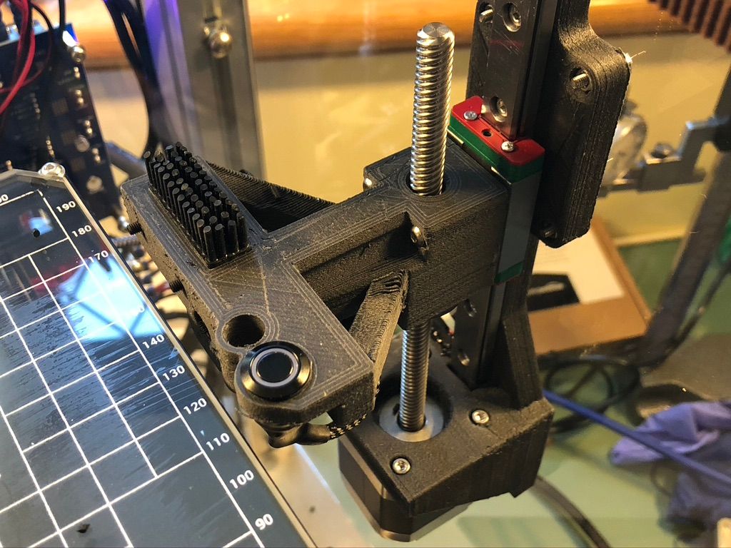
The idea was that the gantry (on axis V) would home to a known absolute position using the microswitch at the bottom of travel (just visible on top of the motor, by the rail).
The tool tip would be centred using a camera and then positioned in XY over the touch switch. I was planning to use
G1 V1 H4 F1000to move the gantry in the upward direction until the switch contacted the tool, then calculate the difference between the absolute position and the calibrated Z0 to get the new tool offset.Unfortunately, setting a second end stop on the V axis seems to overwrite the first? Any suggestions as to how I could work around this bug, please?
-
-
interesting concept. how is the repeatability of the button?
-
Ok, setting and resetting the endstops in the macro allows me to sense the button press but unfortunately
G1 H4doesn't do what I expected. It seems that what it does is travel until the switch is triggered and then sets the user position to the value of the move that was commanded.This means that I lose my original calibration and thus can't calculate a position.
I need a way to move until a switch is triggered without any side effects?
-
@Veti Not able to test yet for this specific manufacturer, but there are commercial machines that use these switches for this purpose, so I expect it to be as repeatable as a microswitch.
-
@Terry said in Auto Tool Height Measurement:
Ok, setting and resetting the endstops in the macro allows me to sense the button press but unfortunately
G1 H4doesn't do what I expected. It seems that what it does is travel until the switch is triggered and then sets the user position to the value of the move that was commanded.This means that I lose my original calibration and thus can't calculate a position.
I need a way to move until a switch is triggered without any side effects?
How about:
H3 terminate the move when the endstop switch is triggered and set the axis limit to the current position, overriding the value that was set by M208.
Then you can use M208 to put things back as they should be.
Frederick
-
H3 appears to do the same as H4, but also changes the min travel extent value.
I think this maybe a bug as that isn't the expected behaviour.
-
@Terry said in Auto Tool Height Measurement:
H3 appears to do the same as H4, but also changes the min travel extent value.
I think this maybe a bug as that isn't the expected behaviour.
If it does that it would seem to be a bug - nothing in the docs suggests it should do that.What firmware version are you using?
I have 3.2.2 and can test that.
Frederick
-
Thanks. I am on 3.2.0 currently and this axis and switches are on a Duet 3 Expansion 3HC board.
-
On a typical CNC platform, I would expect at least 3 triggers per axis.
Endstops would be min and max travel indicators and would be continuously active unless explicitly disabled so they could stop motion before a physical collision (the machine may also include emergency stop cutouts at the physical limits to cut power in a runaway controller scenario). It should be possible to detect unexpected over-travel as a result of lost steps and recover by re-homing.
One or more reference triggers should also exist, for accurate and efficient homing. These should be inboard of the travel limits to avoid harm to the machine during homing operations and may sit in the middle of the travel range to enable efficient re-calibration during long operations. Typically they would only be active during reference operations.
Endstops need to be active during homing in case the assumed start position or travel direction is wrong.
Single active endstop-as-home-reference is a cost-saving hack that is acceptable for a $500 3D printer but can result in injury or physical damage to the machine in larger and more powerful setups, so it would be nice if we could support best practice in the future?
-
@Terry said in Auto Tool Height Measurement:
Thanks. I am on 3.2.0 currently and this axis and switches are on a Duet 3 Expansion 3HC board.
Could you use G60 along with G1 moves with the R parameter to obtain the desired result?
Frederick
Printers: a small Utilmaker style, a small CoreXY and a E3D MS/TC setup. Various hotends. Using Duet 3 hardware running 3.4.6
-
@Terry said in Auto Tool Height Measurement:
Endstops would be min and max travel indicators and would be continuously active unless explicitly disabled so they could stop motion before a physical collision
You can do that with triggers. From one of my printers:
; ****************************************************************************************************
; external buttons (P = pin #, T = trigger #, R = when to trigger (0 = always, 1 = printing), S = what edge (I->A = 1, A->I = 0, -1 = ignored)
; --- T0 does emergency stop
; --- T1 does pause (see M25)
; --- T# runs macro trigger#.g
; ****************************************************************************************************

M950 J2 C"!^duex.e6stop"
M581 P2 T0 R0 S0			; does emergency stop

M950 J1 C"^e0stop"
M581 P1 T2 R0 S0			; runs trigger2 which does M999 (board reset)
Printers: a small Utilmaker style, a small CoreXY and a E3D MS/TC setup. Various hotends. Using Duet 3 hardware running 3.4.6
-
@Terry said in Auto Tool Height Measurement:
Ok, setting and resetting the endstops in the macro allows me to sense the button press but unfortunately
G1 H4doesn't do what I expected. It seems that what it does is travel until the switch is triggered and then sets the user position to the value of the move that was commanded.I think I did not understand what you were saying.
With G1 H4 and G1 H3 the axis is at some position when the end stop is triggered - this position should be what appears in the DWC.
Does that not happen?
Frederick
-
With both
G1 H3andG1 H4, the machine and user positions are overwritten as soon as the switch is triggered. In absolute mode, the axis value is set equal to the destination value that was commanded in the move. In relative mode, the axis position value is set to 1.So, for example, starting at machine coordinate V=50 and commanding
G1 H4 V2, the axis will move towards V=2 but if the switch is pressed before it gets there, motion will stop and the current position of V will be declared to be V=2, changing the calibration. -
@fcwilt G60 wouldn't work because calibration is lost.
-
@fcwilt Triggers can't stop motion in a controlled manner, so at best you can call an emergency stop and lose system calibration. This is why endstop circuitry needs to exist inside the motion control loop - the endstop triggers need to be interrupts that can cancel motion at very low latency without losing position.
-
@Terry said in Auto Tool Height Measurement:
@fcwilt G60 wouldn't work because calibration is lost.
How so?
If you save the current position and then return to it how does that affect calibration?
Frederick
-
G60would store a position relative to the calibration referenced against the fixed endstop. Any move detecting the mobile endstop will cause the axis to re-reference against that position. Any subsequentG2 Rwould return to a saved position relative to the new calibration, so not the original absolute position in the machine framework. -
@Terry said in Auto Tool Height Measurement:
G60would store a position relative to the calibration referenced against the fixed endstop. Any move detecting the mobile endstop will cause the axis to re-reference against that position. Any subsequentG2 Rwould return to a saved position relative to the new calibration, so not the original absolute position in the machine framework.Under firmware 3.2.2 I did a H3 move.
When the end stop was triggered the movement stopped and the M208 setting for Z min was updated using the Z position at the moment the end stop was triggered.
How does that cause the reference for the axis to change?
Frederick
-
But did your machine and user position for that axis also change?