Duet2 wifi + Duex5 for large printer with 4 Z motors
-
first question:
Duet 2 wifi + Duex5 + PanelDue 7i have been assembled and wired.
I tried to power everything with the 12volt 30A power supply and the result was the following.
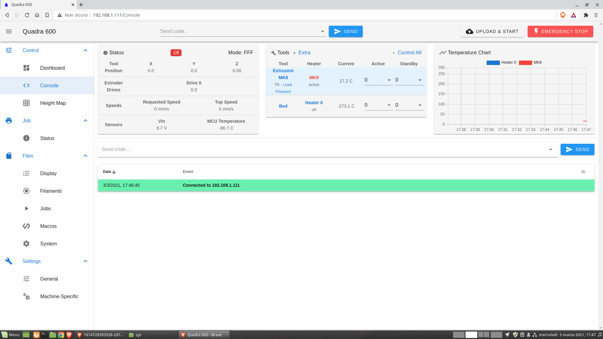
Sensors: VIN = 8.7 V Temperature = -67 C
Current Extrusor temperature= 17.2 CI then replaced the power supply with the 24 volt 15A one and this is the result.
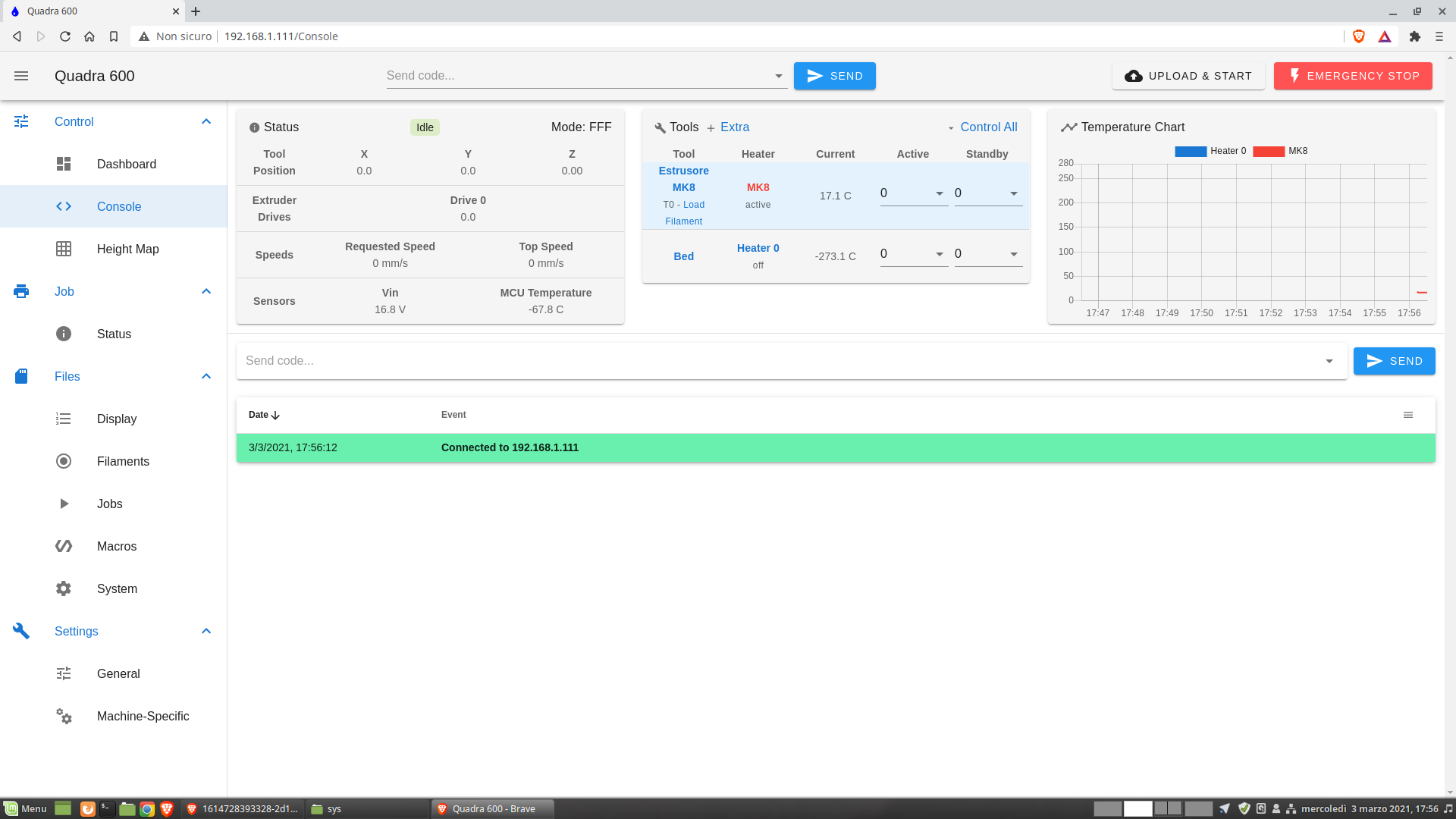
Sensors: VIN = 16.8 V Temperature = -67 C
Current Extrusor temperature= 17.2 CI don't wish there was any problem with the power supplies (both used).
Or some configuration problem!Tips?
M122:
3/3/2021, 18:11:41 M122 === Diagnostics === RepRapFirmware for Duet 2 WiFi/Ethernet version 3.2.2 running on Duet WiFi 1.02 or later + DueX5 Board ID: 0JD0M-9P6M2-NW4SJ-6J1F4-3S46K-KVURM Used output buffers: 3 of 24 (12 max) === RTOS === Static ram: 23460 Dynamic ram: 73792 of which 40 recycled Never used RAM 14788, free system stack 189 words Tasks: NETWORK(ready,179) HEAT(blocked,308) DUEX(blocked,31) MAIN(running,463) IDLE(ready,20) Owned mutexes: WiFi(NETWORK) === Platform === Last reset 00:14:47 ago, cause: software Last software reset at 2021-03-03 17:56, reason: User, GCodes spinning, available RAM 14788, slot 2 Software reset code 0x0003 HFSR 0x00000000 CFSR 0x00000000 ICSR 0x0041f000 BFAR 0xe000ed38 SP 0x00000000 Task MAIN Freestk 0 n/a Error status: 0x00 Aux0 errors 1,1,1 MCU temperature: min -69.6, current -66.6, max -65.9 Supply voltage: min 16.5, current 16.6, max 17.2, under voltage events: 0, over voltage events: 0, power good: yes Driver 0: position 0, standstill, SG min/max not available Driver 1: position 0, standstill, SG min/max not available Driver 2: position 0, standstill, SG min/max not available Driver 3: position 0, standstill, SG min/max not available Driver 4: position 0, standstill, SG min/max not available Driver 5: position 0, standstill, SG min/max not available Driver 6: position 0, standstill, SG min/max not available Driver 7: position 0, standstill, SG min/max not available Driver 8: position 0, standstill, SG min/max not available Driver 9: position 0, standstill, SG min/max not available Driver 10: position 0 Driver 11: position 0 Date/time: 2021-03-03 18:11:40 Cache data hit count 1075011622 Slowest loop: 8.60ms; fastest: 0.21ms I2C nak errors 0, send timeouts 0, receive timeouts 0, finishTimeouts 0, resets 0 === Storage === Free file entries: 10 SD card 0 detected, interface speed: 20.0MBytes/sec SD card longest read time 3.9ms, write time 0.0ms, max retries 0 === Move === DMs created 83, maxWait 0ms, bed compensation in use: none, comp offset 0.000 === MainDDARing === Scheduled moves 0, completed moves 0, hiccups 0, stepErrors 0, LaErrors 0, Underruns [0, 0, 0], CDDA state -1 === AuxDDARing === Scheduled moves 0, completed moves 0, hiccups 0, stepErrors 0, LaErrors 0, Underruns [0, 0, 0], CDDA state -1 === Heat === Bed heaters = 0 -1 -1 -1, chamberHeaters = -1 -1 -1 -1 Heater 1 is on, I-accum = 0.0 === GCodes === Segments left: 0 Movement lock held by null HTTP is idle in state(s) 0 Telnet is idle in state(s) 0 File is idle in state(s) 0 USB is idle in state(s) 0 Aux is assembling a command in state(s) 0 Trigger is idle in state(s) 0 Queue is idle in state(s) 0 LCD is idle in state(s) 0 Daemon is idle in state(s) 0 Autopause is idle in state(s) 0 Code queue is empty. === Network === Slowest loop: 16.61ms; fastest: 0.00ms Responder states: HTTP(0) HTTP(0) HTTP(0) HTTP(0) FTP(0) Telnet(0), 0 sessions HTTP sessions: 1 of 8 - WiFi - Network state is active WiFi module is connected to access point Failed messages: pending 0, notready 0, noresp 0 WiFi firmware version 1.25 WiFi MAC address e0:98:06:a4:6a:92 WiFi Vcc 4.36, reset reason Turned on by main processor WiFi flash size 4194304, free heap 27584 WiFi IP address 192.168.1.111 WiFi signal strength -82dBm, mode 802.11n, reconnections 0, sleep mode modem Clock register 00002002 Socket states: 0 0 0 0 0 0 0 0 === DueX === Read count 1, 0.07 reads/min Config.g
; Communication and general M111 S0 ; Debug off M550 P"Quadra 600" ; Machine name and Netbios name (can be anything you like) ;M552 P192.168.1.111 ; IP address ;M554 P192.168.1.1 ; Gateway ;M553 P255.255.255.0 ; Netmask ;*** End of factory test lines to be removed ;*** Networking M552 S1 ; Turn network on M586 P0 S1 ; enable HTTP M586 P1 S0 ; disable FTP M586 P2 S0 ; disable Telnet M555 P2 ; Set output to look like Marlin G21 ; Work in millimetres G90 ; Send absolute coordinates... M83 ; ...but relative extruder moves ; Drives M569 P0 S1 ; X Axis - physical drive 0 goes forwards M569 P1 S1 ; Y Axis - physical drive 1 goes forwards M569 P3 S1 ; Extrusor - physical drive 3 goes forwards M569 P5 S1 ; Z1 Axis - physical drive 5 goes forwards M569 P6 S1 ; Z2 Axis - physical drive 6 goes forwards M569 P7 S1 ; Z3 Axis - physical drive 7 goes forwards M569 P8 S1 ; Z4 Axis - physical drive 8 goes forwards M584 X0 Y1 Z5:6:7:8 E3 ; set drive mapping M350 X16 Y16 Z16 E16 I1 ; configure microstepping with interpolation M92 X33.33 Y128.00 Z800.00 E420.00 ; set steps per mm M566 X900.00 Y900.00 Z60.00 E120.00 ; set maximum instantaneous speed changes (mm/min) M203 X6000.00 Y6000.00 Z180.00 E1200.00 ; set maximum speeds (mm/min) M201 X500.00 Y500.00 Z20.00 E250.00 ; set accelerations (mm/s^2) M906 X800 Y800 Z800 E800 I30 ; set motor currents (mA) and motor idle factor in per cent M84 S30 ; Set idle timeout ; Axis Limits M208 X0 Y0 Z0 S1 ; set axis minima M208 X602 Y602 Z602 S0 ; set axis maxima ; Endstops M574 X1 S1 P"xstop" ; configure active-high endstop for low end on X via pin xstop M574 Y1 S1 P"ystop" ; configure active-high endstop for low end on Y via pin ystop M574 Z1 S1 P"exp.e5stop + exp.e6stop + exp.e7stop + exp.e8stop" ; configure active-high endstop for low end on Z via pin exp.e5stop ; Thermistors M140 H-1 ; disable heated bed (overrides default heater mapping) ; Heaters M308 S0 P"bedtemp" Y"thermistor" T100000 B4092 ; configure sensor 0 as thermistor on pin bedtemp M950 H0 C"bedheat" T0 ; create bed heater output on bedheat and map it to sensor 0 M307 H0 B1 S1.00 ; enable bang-bang mode for the bed heater and set PWM limit M140 H0 ; map heated bed to heater 0 M143 H0 S120 ; set temperature limit for heater 0 to 120C M308 S1 P"e0temp" Y"thermistor" T100000 B4092 ;A"MK8" ; configure sensor 1 as thermistor on pin e0temp M950 H1 C"e0heat" T1 ; create nozzle heater output on e0heat and map it to sensor 1 M307 H1 B0 S1.00 ; disable bang-bang mode for heater and set PWM limit M143 H1 S280 ; set temperature limit for heater 1 to 280C ; Fans M950 F0 C"fan0" Q500 ; create fan 0 on pin fan0 and set its frequency M106 P0 S0 H-1 ; set fan 0 value. Thermostatic control is turned off M950 F1 C"fan1" Q500 ; create fan 1 on pin fan1 and set its frequency M106 P1 S1 H T45 ; set fan 1 value. Thermostatic control is turned on ; Tools M563 P0 D0 H1 F0 S"Estrusore MK8" ; define tool 0 G10 P0 X0 Y0 Z0 ; set tool 0 axis offsets G10 P0 R0 S0 ; set initial tool 0 active and standby temperatures to 0C ; Miscellaneous M575 P1 S1 B57600 ; enable support for PanelDue M208 S1 Z-0.2 T0 -
@bernardomattiucci said in Duet2 wifi + Duex5 for large printer with 4 Z motors:
I then replaced the power supply with the 24 volt 15A one and this is the result.
i hope you replaced the heater cartridge and the heater on the bed as well
M906 X800 Y800 Z800 E800 I30
are you sure thats 75% of the rated current?
M574 Z1 S1 P"exp.e5stop + exp.e6stop + exp.e7stop + exp.e8stop"
those no the endstops on the duex. they start with duex and go through i2c.
disconnect the paneldue and see if that helps
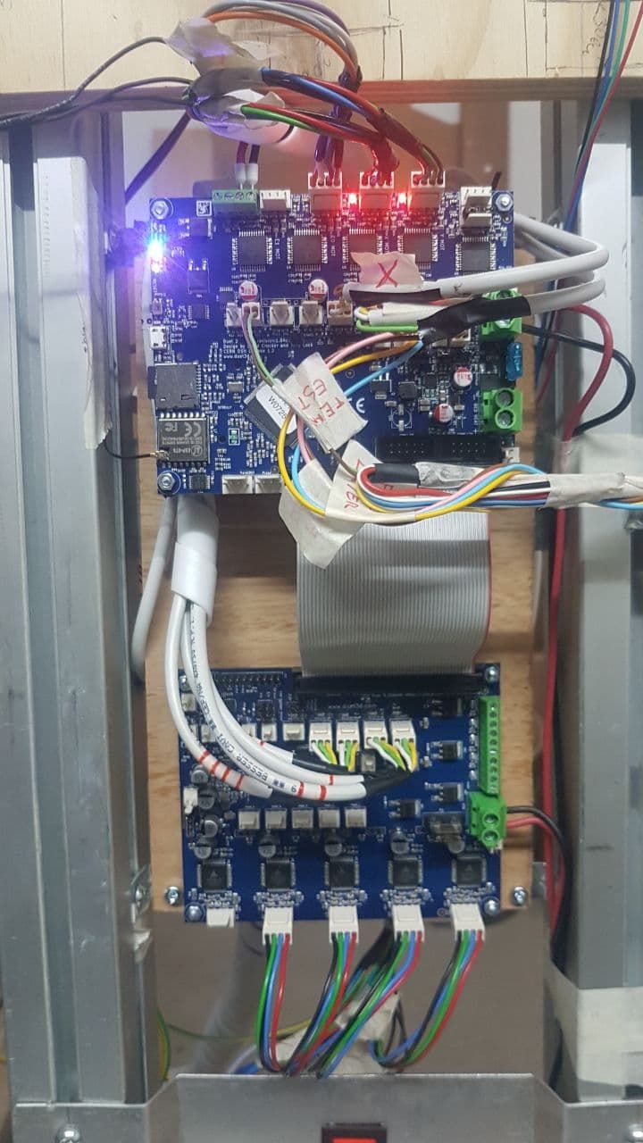
also post a picture of your duet + duex wiring -
By replacing the 12v power supply with the 24v, I hadn't connected anything.
Now I have reassembled the 12v and removed the display.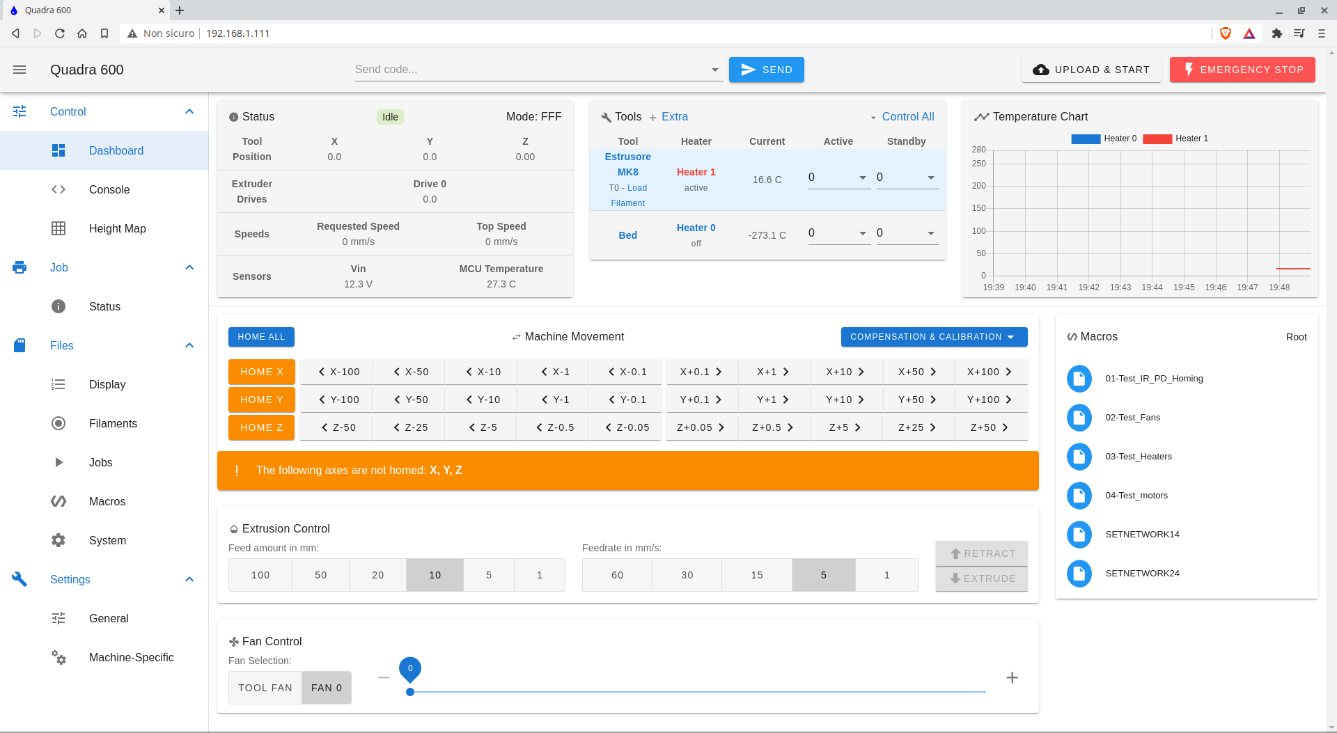
This is the wiring
M906 X800 Y800 Z800 E800 I30
No, I'm not sure of anything. first of all I wanted to understand how it works and fix things as you go. I'll need lots of suggestions ... -
there is the problem that if you connect the paneldue to the wrong header, the voltage will drop.
this seems to have happened for you.
you also did not follow the duex wiring guide. see
https://duet3d.dozuki.com/Wiki/Duex2_and_Duex5_Features#Section_Wiring -
Ok. the problem with the display was that I had connected both cables supplied ... one, to the PanelDue connector (4 wire cable), the other to the LCD connector (not sure why).
The supply voltage is now correct, even with the display on.
I connected the power supply as shown in the photo to the link you suggested (even if the power supply was 30 cm from the boards).
The next step is to understand how to properly set up the motors.
For now I want to try with the 12 volt power supply, waiting to receive the various components (hot-end and fans) at 24 volts. The Hot Bed is, for me, a problem ... in the end I think I will have to use a 220v relay (with 12 or 24volt coil) to power the hot-bed, as, with the current structure of the floor, I have a way to mount heaters. It doesn't matter ... at the moment! -
@bernardomattiucci said in Duet2 wifi + Duex5 for large printer with 4 Z motors:
I connected the power supply as shown in the photo to the link you suggested (even if the power supply was 30 cm from the boards).
there is a big warning on the page
Do not run separate ground wires from each terminal block back to the power supply unless the power supply is very close (less than 100mm) to the Duet 2 and Duex.
so 30 cm is more than 10cm
-
@Veti
Yes, you're right, but I just can't understand why. It does not matter. Now it is OK.The problem now is understanding why the PanelDue works but doesn't seem to interact with the rest of the electronics. Maybe I need to update it?
-
The PanelDue has also been updated.
Now I have to check the engine settings.
Tips? -
@bernardomattiucci said in Duet2 wifi + Duex5 for large printer with 4 Z motors:
Now I have to check the engine settings.
what engine settings?
-
I have to verify the correctness of the settings, both for the stepper motors and for the remapping of the motors.
I have 4 independent motors for the Z axis, each with its own optical sensor (which I am mounting now), placed more or less at the 4 vertices of the XY plane (the printing plane is fixed). I have to make the Z axis move in a coherent way .. reset it using the 4 sensors and manage it properly. -
That's quite easy with RRF3. All you need to do is connect your 4 z endstops, and then define the used pins in the M574 endstop configuration. And home Z as a single axis as normal.
-
Everything starts moving ... and if it weren't for the power supply fan, you wouldn't hear anything (or almost)!
very beautifull!
-
Good morning,
I got to the point where I have to set the zeroing of the Z axis considering the fact that I have 4 motors with 1 endstop each.
in my config.g I have inserted the following instructions:
M584 X0 Y1 Z5: 6: 7: 8 E3 M574 Z1 S1 P "duex.e2stop + duex.e3stop + duex.e4stop + duex.e5stop" and this is my homez.g:
G91 G1 H2 Z5 F6000 G1 H1 Z-607 F360 G92 Z0 How should I proceed?
I'm following these directions:
https://duet3d.dozuki.com/Guide/Independent+Z+motors+and+endstop+switches+in+RRF2/18But it is not very clear to me what I actually have to do and I would not want to be wrong.
In order, the Z axes (Z1, Z2, Z3 and Z4) are positioned as follows:
Z1 = X0 Y0
Z2 = X0 Y600
Z3 = X600 Y600
Z4 = X600 Y0Can you give me some advice?
Thank you
EDIT:
Maybe I need to enter the command
M671 in my config.g?In my case it would be something like:
M671 X-115: -115: 715: 715 y130: 470: 470: 130; Z leadscrews are at
Z2 (-115.130) Z2 (-115.470), Z3 (715.470), Z4 (715.130) -
M584 X0 Y1 Z5: 6: 7: 8 E3
M574 Z1 S1 P "duex.e2stop + duex.e3stop + duex.e4stop + duex.e5stop"delete the spaces
there is no leadscrew location required for this as the endstops determine the position.
just the normal z homing will do it
-
@bernardomattiucci said in Duet2 wifi + Duex5 for large printer with 4 Z motors:
I'm following these directions:
https://duet3d.dozuki.com/Guide/Independent+Z+motors+and+endstop+switches+in+RRF2/18These are for RRF2.
I already linked the instructions for RRF3 above.
-
Good morning
It all seems to work quite well.
Now I just have to figure out how to solve a problem on the Y axis, mostly due to the type of "transmission" used and complete the settings ... before moving on to the print tests!This is the X axis test: https://youtu.be/UG27txKxALk