And with these 5 photos I close the discussion.
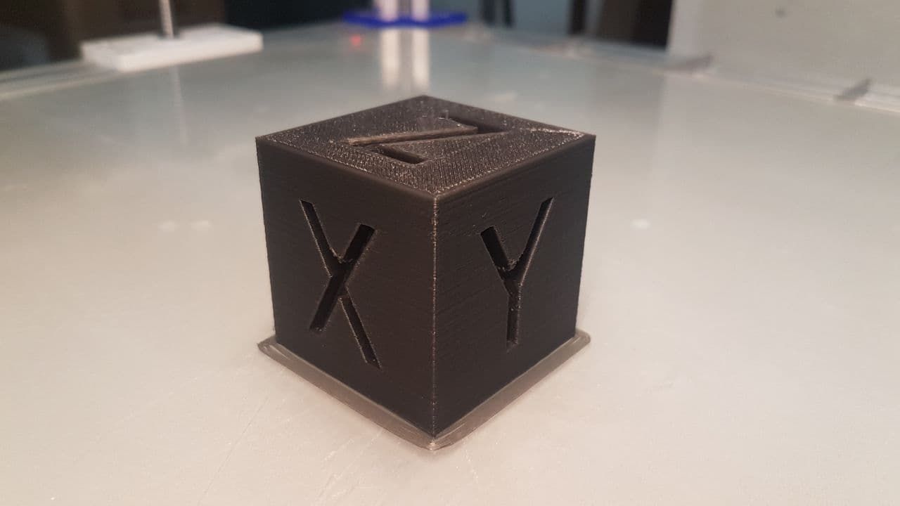
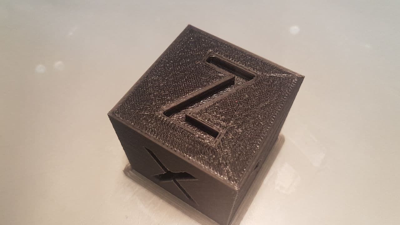
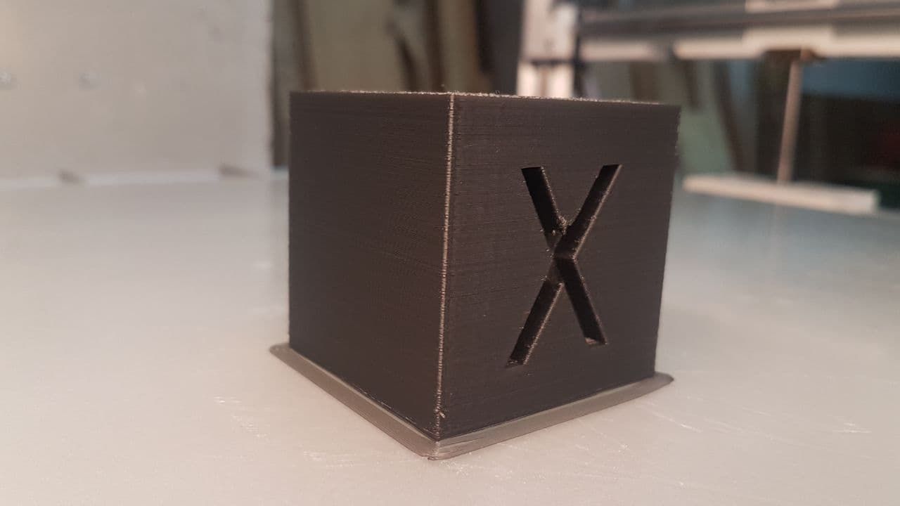
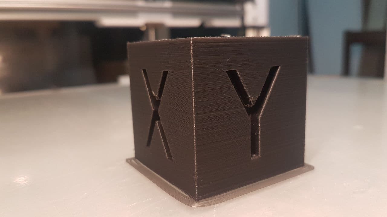
Thank you all
And with these 5 photos I close the discussion.
Thank you all
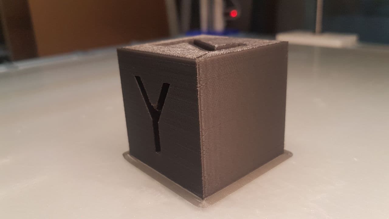
It's not perfect but it's still acceptable.
With a 5x5 or denser map, the result would undoubtedly be better, but having built the 3x3 map entirely by hand, with a series of print runs in succession, I can be satisfied. Also because, I repeat, it is a prototype!
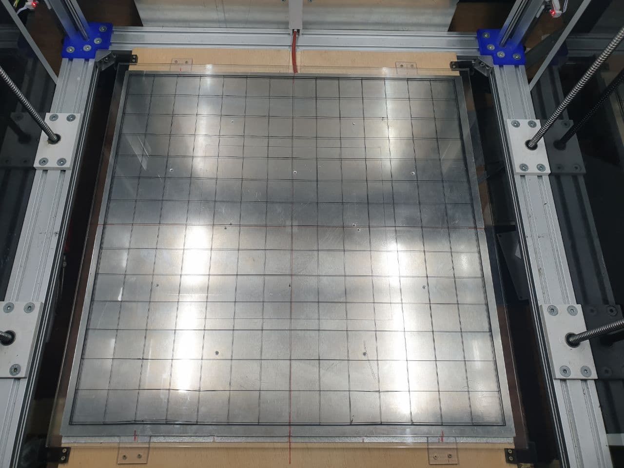
Test grid: 595x595x0.2 with 1% filling (printed in 32 minutes @25-30mm/s)
Everything starts moving ... and if it weren't for the power supply fan, you wouldn't hear anything (or almost)!
very beautifull!
Goodmorning everyone
I had entered the codes M566, M203 and M201 in the config.g file to find the speed "limits" of the X and Y axes.
Now the 3 instructions in the file have been commented out.
From the Console I get this:
Custom M566
;M566 X4000.00 Y4000.00 Z300.00 E1500.00           										; set maximum instantaneous speed changes (mm/min)

Original M566
Maximum jerk rates (mm/min): X: 900.0, Y: 900.0, Z: 12.0, E: 120.0, jerk policy: 0

Custom M203
;M203 X20000.00 Y20000.00 Z1000.00 E5000.00       										; set maximum speeds (mm/min)

M203
Max speeds (mm/min): X: 6000.0, Y: 6000.0, Z: 300.0, E: 1200.0, min. speed 30.00

Custom M201
;M201 X5000.00 Y5000.00 Z100.00 E4000.00           										; set accelerations (mm/s^2)

M201
Accelerations (mm/sec^2): X: 500.0, Y: 500.0, Z: 20.0, E: 250.0
I'll do some printing tests with the default values and let you know.
@fcwilt At the moment I cannot change anything, so I would like to use compensation. The problem is that the compensation doesn't seem to work... because on the left side it manages to give me a relatively acceptable height in relation to the plane, while on the right side it doesn't. And I don't understand why.
Tomorrow I will try to modify the map manually, so that I can "force" the compensation only on the right side of the plate.
The new deck is being designed, but it requires structural modifications that I cannot install on this one due to lack of space. I will also have to completely redo the Y-axis, which in this way has limitations that I don't like. But we'll talk about that in late spring!
Good morning
It all seems to work quite well.
Now I just have to figure out how to solve a problem on the Y axis, mostly due to the type of "transmission" used and complete the settings ... before moving on to the print tests!
This is the X axis test: https://youtu.be/UG27txKxALk
@fcwilt Yes, I know that, but at the moment I am not interested in exceptional quality. I just want it to print what I want, how I want it and without too many mistakes.
I will slowly replace the various "definitive" PLA parts with aluminium alloy equivalents, so that all the mechanics become more stable. At that point, having in the meantime replaced the round guides (X and Z with MGN15 recirculating ball bearings), I will be able to create the 20x20 mesh.
Thank you
I fixed the errors in the code.
if job.build != null
	if job.layer != null && job.layer <= 5
		M140 S50
	elif job.layer != null && job.layer > 5
		if job.layer < 20
			if heat.heaters[0].current < 40
				M140 S50
			if heat.heaters[0].current > 50
				M140 S40
		else
			M140 S0
if job.build != null
	if job.layer != null && job.layer <= 5
		M140 S50
	elif job.layer != null && job.layer > 5
		if ((job.file.numLayers*20)/100) < 20
			if heat.heaters[0].current < 40
				M140 S50
			if heat.heaters[0].current > 50
				M140 S40
		else
			M140 S0
seems to be working
I removed the cover and the problem does not occur.
I reassembled it, paying attention to how the wiring was being locked, and so far it has not given me any errors.
What I would like to understand, however, is the logic behind the error.
On the head we get the wiring for the extruder (motor, sensor, fan), accelerometer, bltouch, fan layer, and led lights. Plus 3 other wires that are not used.
Why should I have a problem with the layer temperature sensor?
@Phaedrux No graph. The plan is disabled. Cold plate mold. And that's why I don't understand....
Hello everyone,
today I was mounting a protective cover on the head of my printer, so as to cover the connections of the various cables. I had the printer on, because I didn't think it would be that much trouble to do it (I only had to tighten 2 M3 bolts).
The connections include:
I placed the cover and started screwing in the bolts, but at some point on the duet's display, the platen temperature sensor went “fault.”
The error gave me several times, but I still didn't understand why.
I would like to understand the logic so I can possibly detect some short--because then it worked and never gave me any error again.

Unfortunately, the printing has stalled again, at about 87 percent.
There is one thing to be said, however: I am printing in too cold an environment. Although my printer is closed, the printing chamber today never got above 18°C (I have no heating here in the attic). And I can't afford to keep the 1200Watt heated top on for 8 hours!!!!
Will I have to wait a few months? 
I'm noticing some flaws -- due to poor retraction. But these are flaws I can accept. The important thing is to print.
Maybe I'll increase to 0.7 mm for tomorrow's next print.
I am just now doing my second print test, with a second filament that was giving me continuous problems.
The problems I was experiencing were “blockages” in the extrusion, not dependent on excessive temperature, but on failure to extrude. That is, the filament could not get out and as the extruder kept pushing, the filament was being “eroded” at the extruder drive wheel. Why does this happen?
Maybe because the settings were wrong. I had gotten a very good result with a very good PLA filament, which is now finished, and the same settings did not apply to these other filaments. And it was driving me crazy, because if I paused the printer and manually extruded some filament, it was extruded without any problem, except for the “mechanical” thinning generated by the failed extrusion.
M207
Tool 0 retract/reprime: length 0.60/0.60mm, speed 55.0/60.0mm/sec, Z hop 0.10mm
So?
Reading the last comment, this morning I set the firmware retraction to 0.6mm and everything seems to be fine.
As a result... with 1mm, the extruder retracted the filament, but failed to send it completely back into place within the set time. And that, in the long run, created a problem that resulted in filament blockage--due essentially to the overlap, I think, of 2 extrusion commands. Or something like that.
My last setting. I'll try it tomorrow.
M207
Tool 0 retract/reprime: length 1.00/1.00mm, speed 55.0/60.0mm/sec, Z hop 0.10mm
@Notepad
Yesterday I set the following values and ran some tests that went very well.
M207
Tool 0 retract/reprime: length 1.00/1.00mm, speed 40.0/40.0mm/sec, Z hop 0.00mm
The problem occurs when the print lasts longer than 1 hour...at which point the filament tends to get stuck.
At this point the possibilities are 2:
I have constant problems with some cheap filaments, especially after a number of retractions, and I was redoing the setup of my IdeaMaker slicer.
Launching the M207 command, I realized that there were already default pre-settings and I was wondering--to disable firmware retraction, what should I do?
M207
Tool 0 retract/reprime: length 2.00/2.00mm, speed 16.7/16.7mm/sec, Z hop 0.00mm
In your opinion, would it be possible on the Duet 2 wifi to use several different compensation meshes during the same print?
Let me explain further:
My plane is 615x615 mm, and with the limit of 441 points for the grid, the “resolution” of the mesh is very low.
Having an unplanar plane, I made 2 different meshes, one full-width and one for an area of 200x200 mm.
I was thinking that, maybe with a script in daemon.g, it would be possible to dynamically swap the active mesh. If it were possible I would proceed to make a series of 3x3 200x200mm meshes, which would be dynamically and automatically loaded when needed when printing.
Do you think this is possible?
Alternatively, perhaps a dynamic system could be created, which provides data for an area of XxY mm around the hot-end, drawing on a previously made high-resolution mesh.
But again, I don't know if this is feasible.
