Y bed and Endstop offset?
-
Hi Everyone,
Im an absolute amature when it comes to firmware, so please excuse me but I am trying to learn. Im having an issue with positioning the print head and endstops, and Im assuming I need to put in some type of offset. My printer is a CR10 S5 (cartisian with 510x510 bed size, print area 500x500). I bought a linear rail kit from 3Dfused, but Im having a serious issue with the bed positioning.If I home the Y axis and take this position as 0. Then mark the actual center of the bed with a marker, the printer needs to be at Y287 to actually be center of the bed. The issue with doing this means that if I try to move the full length of the bed (Y500) i run out of space at Y467 .
The actual rail lengths are 650mm.At first I thought maybe the motor esteps were off, but Ive tried printing as big as 360x340 as a test and dimensionally the print is perfect. So I dont believe its the esteps and more has to do with how the firmware is recording the endstop and bed positioning.
My current config:
; Drives
M569 P0 S0                                ; physical drive 0 goes forwards
M569 P1 S1                                ; physical drive 1 goes forwards
M569 P2 S1                                ; physical drive 2 goes forwards
M569 P3 S1                                ; physical drive 3 goes forwards
M584 X0 Y1 Z2:4 E3		  	; two Z motors connected to driver outputs Z and E1
M671 X-20:220 Y0:0 S0.5 	     	; leadscrews at left (connected to Z) and right (connected to E1) of X axis
M208 X-5:205 Y0:200 		    	; X carriage moves from -5 to 205, Y bed goes from 0 to 200
M350 X16 Y16 Z16 E16 I1                   ; configure microstepping with interpolation
M92 X80.00 Y80.00 Z400.00 E408          ; set steps per mm
M566 X500.00 Y500.00 Z24.00 E300.00     ; set maximum instantaneous speed changes (mm/min)
M203 X12000.00 Y12000.00 Z300.00 E3600.00 ; set maximum speeds (mm/min)
M201 X500.00 Y500.00 Z100.00 E5000.00     ; set accelerations (mm/s^2)
M906 X800 Y800 Z900 E800 I30            ; set motor currents (mA) and motor idle factor in per cent
M84 S30                                 ; Set idle timeout

; Axis Limits
M208 X5 Y-37 Z-2.5 S1                    ; set axis minima
M208 X500 Y463 Z500 S0                  ; set axis maxima

; Endstops
M574 X1 Y1 S1                           ; set active high endstops
M574 Z1 S2                              ; set endstops controlled by probe

; Z-Probe
M558 P9 H5 F120 T6000 A2                ; set Z probe type to bltouch and the dive height + speeds
G31 P500 X-30.8 Y0 Z2.55                ; set Z probe trigger value, offset and trigger height
M557 X15:445 Y15:445 S20                ; define mesh grid

; Heaters
M305 P0 T100000 B4138 R2200             ; set thermistor + ADC parameters for heater 0
M143 H0 S120                            ; set temperature limit for heater 0 to 120C
M305 P1 T100000 B4138 R2200             ; set thermistor + ADC parameters for heater 1
M143 H1 S280                            ; set temperature limit for heater 1 to 280C

; Fans
M106 P0 S1 I0 F500 H1 T30               ; set fan 0 value, PWM signal inversion and frequency. Thermostatic control is turned on
M106 P1 S1 I0 F500 H1 T45               ; set fan 1 value, PWM signal inversion and frequency. Thermostatic control is turned on

; Tools
M563 P0 D0 H1 F0                        ; define tool 0
G10 P0 X0 Y0 Z0                         ; set tool 0 axis offsets
G10 P0 R0 S0                            ; set initial tool 0 active and standby temperatures to 0C
Any suggestions on how I fix this so that I can actually use the full extent of my bed?
-
; Axis Limits
M208 X5 Y-37 Z-2.5 S1                    ; set axis minima
M208 X500 Y463 Z500 S0                  ; set axis maxima
37+463=500
So you've got it so that when the Y endstop is hit, it's telling the firmware that the nozzle is 37mm off the edge of the bed, but you're also telling it that from the edge of the bed onward it can only go 463mm. That should be the full 500mm shouldn't it?
-
@Phaedrux well thats what I thought... but the problem is that if I make the endstop 0 and tell it to move to Y250 Im well off the center of the bed.
I am understanding that I have the 500mm in movement, but if I had to try and print a 500x500 block for arguements sake, Id be well off the bed. How do I get the firmware or the slicer understand the positioning correctly? -
let me try explain it this way.
X0 Y0 should be the front left of my bed. I have made a mark 10mm in from each side given that the bed is actually 510 by 510.
My X and Y coordinates are actually X5 Y6 when I position the nozzle over this point on the bed
My X endstop on the X actually hits at X5 so it recording a position of X5 would make it 10 which is correct mathematically, but will mean that everything actually prints 5mm to the left.
Frankly Im just lost on the Y
-
What I mean is that your Y maxima should be 500 if you bed size is a full 500. If the nozzle is 37mm off the edge of the bed when the endstop is triggered, that's fine, and the minima can be -37, but if the actual bed size is 500mm long than the maxima still needs to be 500, not 463.
Maybe I'm not understanding what you're saying.
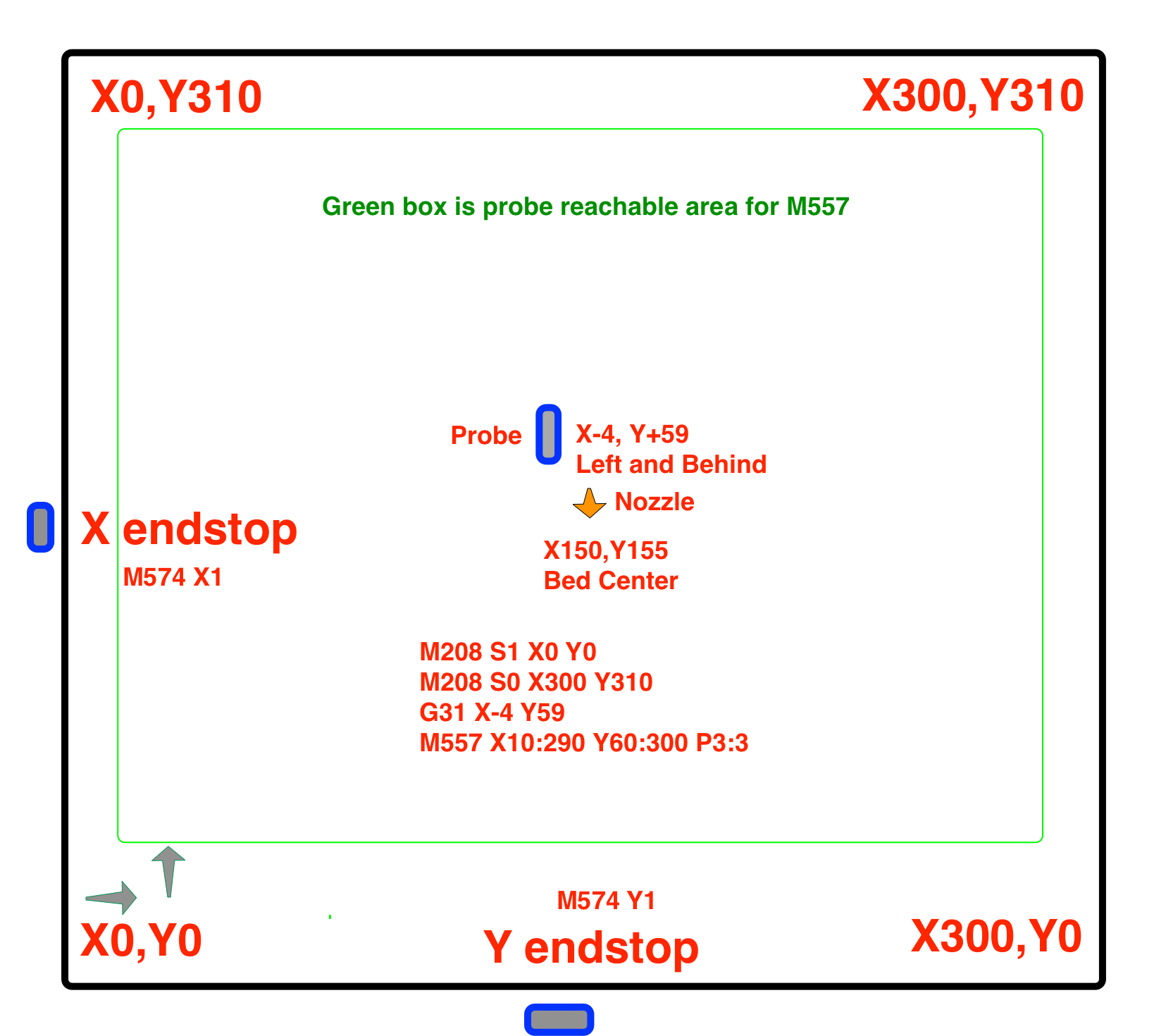
Try drawing up a diagram like this
It can also help to measure your bed size by moving the nozzle to the front left corner and sending G92 X0 Y0, then you can jog the head around to the extents of travel and note the coordinates. Use M564 S0 H0 to allow all movement.
That way you can get the true size of the bed and actual positions of the endstops when they trigger relative to that 0,0 point. Set your M208 minima and maxima accordingly.
-
Ahh ok I see what you are saying. So the issue and why I set the maxima to 467 was simple. Past that you run out of room to move. If I change the maxima to 500, anything past the 467 causes the rails to hit the end of the rail and cant move past. So the 467 is the physical limit of it.
-
@GT1Za said in Y bed and Endstop offset?:
X0 Y0 should be the front left of my bed. I have made a mark 10mm in from each side given that the bed is actually 510 by 510.
If the bed is 510 x 510 shouldn't the marks be made at 5mm in from each edge? 510 - (10 + 10) is 490.
My X endstop on the X actually hits at X5 so it recording a position of X5 would make it 10 which is correct mathematically, but will mean that everything actually prints 5mm to the left.
You can adjust your axis min/max values to account for actual endstop position but there is another way.
For this example assume X min is set to 0, X max is set to 500 and the endstop sensor triggers at X = 5.
G91              ; relative moves
G1 H1 X-520 Faaa ; move toward the endstop at a "fast" speed (sets X position to X min)
G1 X20           ; back off enough so endstop is not triggered
G1 H1 X-30 Fbbb  ; move again toward the endstop at a "slow" speed to improve accuracy
G90              ; absolute moves
G92 X5           ; set the X position to the actual position where the endstop triggered
Frederick