Is there a way to debug accelerometer connection issues?
-
Board: Duet 2 WiFi (2WiFi)
Firmware: RepRapFirmware for Duet 2 WiFi/Ethernet 3.3beta3 (2021-04-22)I've got a couple of accelerometers and believe I've carefully followed the connection instructions, but I can't get RRF to recognize the accelerometer.
I've done a continuity test on all connections and I'm using about 400mm of shielded 9 core cable.
However I get the following error

Is there any way of further debugging the issue?
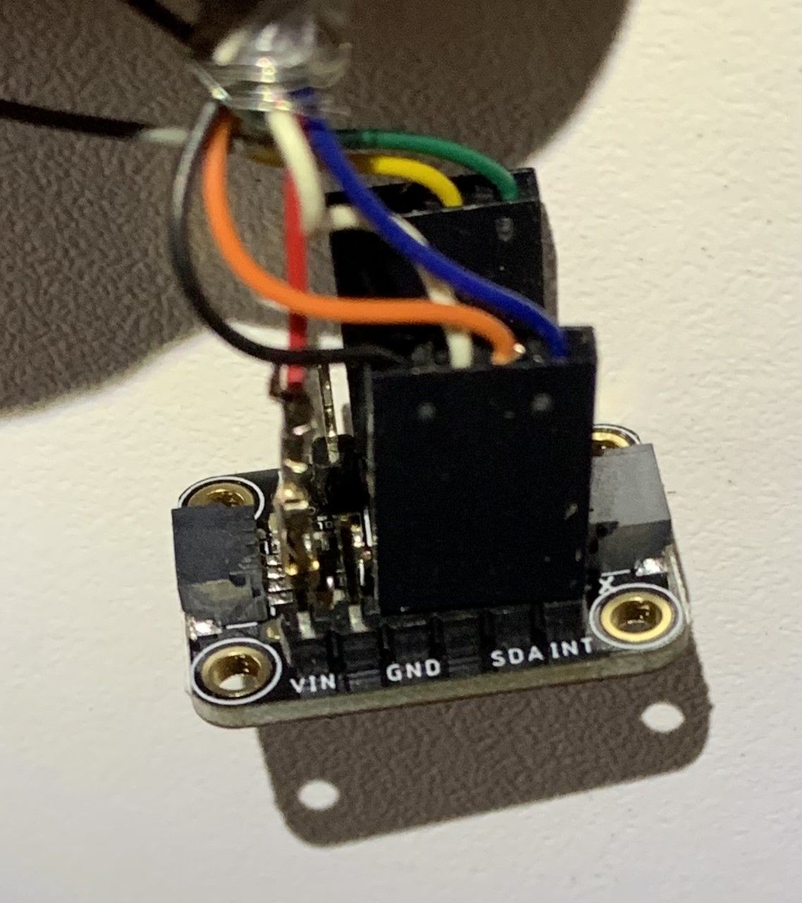
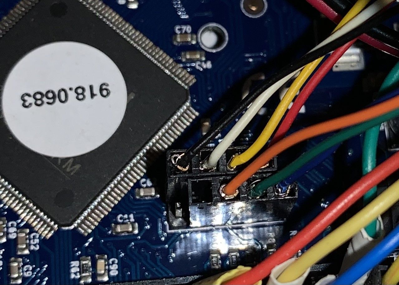
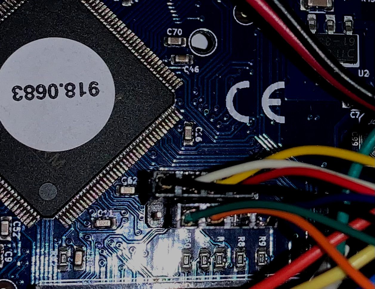
I've tried both accelerometers.Here is my wiring
Here is config.g
; Configuration file for Duet WiFi (firmware version 3) ; executed by the firmware on start-up ; ; generated by RepRapFirmware Configuration Tool v2.1.4 on Sat Jan 04 2020 09:46:45 GMT+1000 (Australian Eastern Standard Time) ; serial comms / Paneldue M575 P1 B57600 S1 ; General preferences G90 ; send absolute coordinates... M83 ; ...but relative extruder moves M550 P"3Dprinter" ; set printer name ; Network M554 P192.168.1.1 ; set gateway M553 P255.255.255.0 ; set netmask M552 S1 P"DARE" ; enable network M586 P0 S1 ; enable HTTP M586 P1 S1 ; enable FTP M586 P2 S1 ; enable Telnet ; Drives M569 P0 S1 ; physical drive 0 (X) goes forwards M569 P1 S0 ; physical drive 1 (Y) goes backwards M569 P2 S1 ; physical drive 2 (Z) goes forwards M569 P3 S0 ; physical drive 3 (E0) goes backwards M584 X0 Y1 Z2:4 E3 ; two Z motors connected to driver outputs Z and E1 M671 X-74:240 Y79:79 S5.5 ; leadscrews at left (connected to Z) and right (connected to E1) of X axis M350 X16 Y16 Z16 I1 ; Configure microstepping with interpolation for XYZ M350 E16 I1 ; Configure microstepping with interpolation for E0 M92 X100.00 Y100.00 Z400.00 ; set steps per mm XYZ M92 E854 ; set E steps/mm for Titan Aero ; axis settings M98 P"0:/sys/set_max_speeds.g" ; set all the max speeds in macro as these are adjusted during home moves so we only want to adjust in one spot M906 X1100 Y1100 Z1100 E1400 I30 ; set motor currents (mA) and motor idle factor in per cent M84 S30 ; Set idle timeout ; Axis Limits M208 X0:215 Y0:198 Z0:180 ; X carriage moves from 0 to 200, Y bed goes from 0 to 198 ; Endstops M574 X1 S1 P"xstop" ; configure active-high endstop for low end on X via pin xstop M574 Y1 S1 P"ystop" ; configure active-high endstop for low end on Y via pin ystop M574 Z1 S2 ; configure Z-probe endstop for low end on Z ; Z-Probe M950 S0 C"exp.heater3" ; create servo pin 0 for BLTouch ;M558 P9 C"^zprobe.in" H6 F180:60 T2400 A10 S0.03 R0.5 B0 ; set Z probe type to bltouch and the dive height + speeds M558 P9 C"^zprobe.in" H6 F600:180 T2400 A10 S0.03 R0.5 B0 ; set Z probe type to bltouch and the dive height + speeds G31 P500 X27 Y-2 Z0.48 ; set Z probe trigger value, offset and trigger height M557 X30:200 Y10:180 S30 ; define mesh grid ;Calculate bed centre ;global Bed_Center_X =move.compensation.probeGrid.maxs[0]-move.compensation.probeGrid.mins[0])/2) + move.compensation.probeGrid.mins[0] - sensors.probes[0].offsets[0] ;global Bed_Center_Y = (move.compensation.probeGrid.maxs[1]-move.compensation.probeGrid.mins[1])/2) + move.compensation.probeGrid.mins[y] - sensors.probes[0].offsets[1] ; Heaters M308 S0 P"bedtemp" Y"thermistor" A"Bed" B3950 C7.06e-8 ; configure sensor 0 as thermistor on pin bedtemp M950 H0 C"bedheat" T0 Q10 ; create bed heater output on bedheat and map it to sensor 0 and set PWM frequency to 10hz M140 H0 ; Set bed themp to zero M143 H0 S130 A0 C0 ; set temperature limit for heater 0 to 130C - fault if too high M308 S1 P"e0temp" Y"thermistor" A"Nozzle-1" B4725 C7.06e-8 ; configure sensor 1 as thermistor on pin e0temp M950 H1 C"e0heat" T1 ; create nozzle heater output on e0heat and map it to sensor 1 M143 H1 S285 A0 C0 ; set temperature limit for heater 1 to 280C - fault if too high ;echo "sensor create time: " ^ state.upTime ^ "." ^ state.msUpTime ; Set PID autotune parameters M307 H0 R0.553 C379.7 D21.16 S0.80 B0 V0 M307 H1 B0 R1.594 C358.1:217.5 D6.05 S1.00 V24.3 ;set PID values for heater 1 (hotend) ; Joystick M308 S3 P"exp.thermistor4" Y"linear-analog" A"JoyStick-X" F1 B100 C-100 ; set analog input on E3 Temp with min/max of -100 to 100 M308 S4 P"exp.thermistor6" Y"linear-analog" A"JoyStick-Y" F1 B100 C-100 ; set analog input on E5 Temp with min/max of -100 to 100 M581 T7 P7 ; set up trigger for GpIn 7 M950 J7 C"!^exp.31" ; Input 7 uses Expansion 31 pin activate pullup and inverted ; Servos and input/output M950 P5 C"exp.e5_stop" ; Output 5 uses E5_STOP pin M950 J6 C"exp.e6_stop" ; Input 6 uses E6_STOP pin ; Filament monitor M591 P1 C"e0stop" S1 D0 ; filament monitor for extruder 0 connected to E0 endstop ; Fans M950 F0 C"fan0" Q50 ; create fan 0 on pin fan0 and set its frequency M106 P0 C"Part_Fan" S0 B2.0 H-1 ; set fan 0 name and value. Thermostatic control is turned off ; Adjust MCU temp reading to match ambient ;water pump M950 F1 C"!fan1+^exp.pb6" Q25000 ; create fan 1 (water pump) on inverted pin fan1 and set its frequency. Set RPM to E3 stop with pullup enabled M106 P1 C"Water Pump" H1 L0.5 X1 B1.2 T50:60 ; set fan 1 name and value. Thermostatic control is turned on. Monitoring hoted sensor ; water temp monitor & fan M950 F2 C"!fan2+^exp.e3_stop" Q25000 ; create fan 2 on pin fan2 and set its frequency M308 S5 P"e1temp" Y"thermistor" A"Water temp" T10000 B3950 ; Configure Water temp sensor M106 P2 C"Radiator Fan" H5 L0 X1 B1.2 T33:38 ; set fan 4 value, turn on at 30% if the water temperature reaches 30C, and increase to full speed gradually as the temperature rises to 40C ; MCU temp sensor M308 S2 P"mcu-temp" Y"mcu-temp" A"Duet Board" ; Configure MCU sensor ; Calibrate MCU temp M912 P0 S-4 ; Tools M563 P0 S"Extruder1" D0 H1 F0 ; define tool 0 G10 P0 X0 Y0 Z0 ; set tool 0 axis offsets G10 P0 R0 S0 ; set initial tool 0 active and standby temperatures to 0C ; Global Variables for heater checking routine in daemon.g while heat.heaters[1].current = 2000 ; loop until thermistor values are stable G4 P1 if iterations > 10000 ; if it takes more than 10 seconds we have a problem with the thermistor M118 P0 L1 S"Thermistor failed to stabilize in less than 10 seconds" break ;echo "sensor stable time: " ^ state.upTime ^ "." ^ state.msUpTime if !exists(global.LastTemp) global LastTemp = heat.heaters[1].current ; Set variable to current extruder temp. else set global.LastTemp = heat.heaters[1].current ; Set variable to current extruder temp. if !exists(global.LastCheckTime) global LastCheckTime = 0 ; variable for use in daemon.g else set global.LastCheckTime = 0 ; variable for use in daemon.g ;Select tool zero T0 P0 ; extrusion if !exists(global.LoadedFilament) ; global variable to hold filament name global LoadedFilament = "No_Filament" ; create a filament variable if move.extruders[state.currentTool].filament="" echo "No filament loaded. Cold extrude & retract set to defaults" M302 S190 R110 ; Allow extrusion starting from 190°C and retractions already from 110°C (defaults) set global.LoadedFilament = "No_Filament" else set global.LoadedFilament = move.extruders[state.currentTool].filament ; set the variable to the currently loaded filament echo "Loading config for " ^ global.LoadedFilament ^ " filament" M703 ; if a filament is loaded, set all the heats and speeds for it by loading config.g ; Custom settings M376 H4 ; set bed compensation taper (H4 means taper over 4mm) ; Power failure recovery M911 S22.5 R23.0 P"M42 P5 S0 M106 P0 S0 M913 X0 Y0 G91 M83 G1 Z3 E-2 F1000" ; If power drops below 22v then turn off fans, Set X & Y current to zero, raise head, retract. ; turn on LED strip driven by P5 output M42 P5 S1 ;Valve Control test to control servo position via fan speed ; Set up scaling variables {(output_end - output_start) / (input_end - input_start)} ;M950 S1 C"exp.heater4" ; assign GPIO port 0 to heater4 on expansion connector, servo mode if !exists(global.InputStart) global InputStart = 0 if !exists(global.InputEnd) global InputEnd = 1 if !exists(global.OutputStart) global OutputStart = 0 if !exists(global.OutputEnd) global OutputEnd = 180 if !exists(global.ScaleFactor) global ScaleFactor = (global.OutputEnd - global.OutputStart) / (global.InputEnd - global.InputStart) ; no need for the math in this instance but it makes it clear how you arrive at the value. if !exists(global.ServoOut) global ServoOut = floor(global.ScaleFactor * (fans[0].actualValue - global.InputStart) + 0.5) + global.OutputStart ; calculate position required on sevo - use floor() to apply rounding ;M280 P1 S{global.servo_out} ; adjust valve position to reflect fan speed. ;play startup tune G4 S8 ; Allow time for PanelDue to start & wifi connection etc M98 P"0:/macros/songs/itchyscratchy.g" ; Play tune M501 ; load config-overide.g ; configure accelerometer M955 P0 C"spi.cs3+spi.cs4" ; configure accelerometer -
I've now tried the cable on an Arduino and it works.
The only difference is that arduino doesn't use INT pin -
If the INT pin is not connected then the accelerometer will still be detected, but collecting data won't work.
What SPI clock rate did you use when testing it with the Arduino? Duet uses 4MHz.
In your photos, the VIN pin of the sensor breakout board does not appear to be connected, so the board will not receive power in the correct manner (unless there is another VIN pin on the other side).
-
@dc42 said in Is there a way to debug accelerometer connection issues?:
If the INT pin is not connected then the accelerometer will still be detected, but collecting data won't work.
What SPI clock rate did you use when testing it with the Arduino? Duet uses 4MHz.
I don't rightly know.
I just followed this tutorial and set it for software SPI.
https://learn.adafruit.com/adafruit-lis3dh-triple-axis-accelerometer-breakout/arduino
I was able to get data from both the acceldemo and tap demo.In your photos, the VIN pin of the sensor breakout board does not appear to be connected, so the board will not receive power in the correct manner (unless there is another VIN pin on the other side).
VIN is connected (red wire) , it's just that I only had 4pin housings so it's just a single wire straight onto the header pin.
It's a bit hard to see in the photo.
The LED on the breakout board lights up indicating it's powered up. -
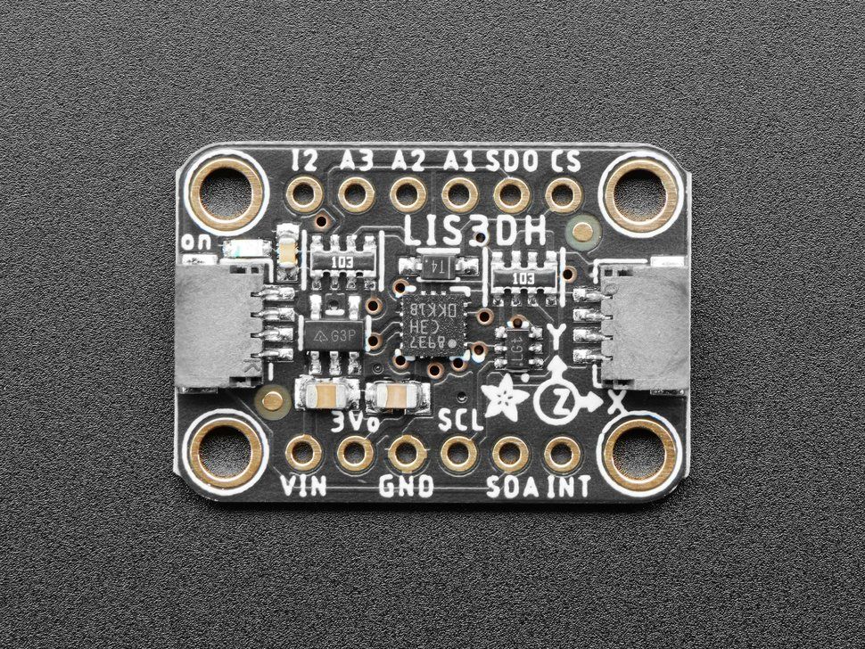
OK, I see the pin connection now. Is that the newer version of the Adafruit board? What is the pin between GND and SDA (white wire)?
-
PS - you initially had this according to the error message:
M955 P0 C"spi.cs4+spi.cs3" ; configure accelerometer
but your config.g has this:
M955 P0 C"spi.cs3+spi.cs4" ; configure accelerometer
Which are you using? I think spi.cs3+spi.cs4 is correct for your wiring scheme.
-
@dc42 the white wire is the SCL pin
-
@dc42 said in Is there a way to debug accelerometer connection issues?:
PS - you initially had this according to the error message:
M955 P0 C"spi.cs4+spi.cs3" ; configure accelerometer
but your config.g has this:
M955 P0 C"spi.cs3+spi.cs4" ; configure accelerometer
Which are you using? I think spi.cs3+spi.cs4 is correct for your wiring scheme.
I had originally tried M955 P0 C"spi.cs3+spi.cs4" per my config.
When I was running out of ideas, I tried reversing it. I must have picked up the error message from the latter.This breakout board has QT connections available. Otherwise it's identical.
OK, I see the pin connection now. Is that the newer version of the Adafruit board? What >is the pin between GND and SDA (white wire)?
The pin between VIN and GND says 3V. I had been using VIN, but as that would be 5V on the arduino and 3V on the duet, I just tried again using the 3V pin.
Same result. Unit powers up, but is not found.
Data sheet
https://cdn-learn.adafruit.com/assets/assets/000/085/846/original/lis3dh.pdf?1576396666Schematic
https://learn.adafruit.com/assets/94435The data sheet says that the CS pin must be brought low to enable SPI and it defaults to I2C
Could this be the issue? -
Have you tried using a different Duet pin to connect CS to? E.g. spi.cs1
-
@dc42 said in Is there a way to debug accelerometer connection issues?:
Have you tried using a different Duet pin to connect CS to? E.g. spi.cs1
Just tried it.
Moved green wire (CS) to spi.cs1
Same result.

On a side note, there seem to be two wiring diagrams floating around.
One says it's CS1 and the other CS0https://d17kynu4zpq5hy.cloudfront.net/igi/duet3d/JPWtqVWwLBxCAKyP.huge
https://d17kynu4zpq5hy.cloudfront.net/igi/duet3d/vqBUAZPsxMC5tRgt.huge
The one that says CS0 can be found here
https://duet3d.dozuki.com/Guide/2.)+Wiring+your+Duet+2+WiFi-Ethernet/9 -
OK.
I just tried wiring directly to the LIS3DH using 150mm jumpers and it works!

Strange that the other cable works on an arduino.
Would it be better to use cable that has twisted pairs?
I thought the shielded cable would be a good option. -
@owend What kind of cable are you using? Another user and I had good success with USB 3 cables (mine is 3m long).
-
@diamondback
I was using 9 core shielded
https://www.altronics.com.au/p/w2712-9-core-shielded-data-cable/I'm about to try some CAT5 data cable (4 x twisted pairs)
I'll report back. -
@owend Ok, I tried single twisted pairs first, ie basically the inner part of CAT 5 cable without any shielding, and that didn't work for me. The USB cable is both twisted and shielded multiple times, I connected all the shielding to GND as well.
-
Success!
For me a piece pf CAT5E cable worked.
I'm reasonable confident the connections on the first cable are sound.
Perhaps a better choice would be the USB cables suggested or maybe CAT6 shielded cables?Now I have some data...
Just have to work out what to do with it
-
@owend said in Is there a way to debug accelerometer connection issues?:
Success!
For me a piece pf CAT5E cable worked.
I'm reasonable confident the connections on the first cable are sound.
Perhaps a better choice would be the USB cables suggested or maybe CAT6 shielded cables?Now I have some data...
Just have to work out what to do with itAwesome!

-
@owend said in Is there a way to debug accelerometer connection issues?:
Perhaps a better choice would be the USB cables suggested or maybe CAT6 shielded cables?
An oscilloscope would allow you to look at the signals and see if they are missing or distorted.
-
@zapta said in Is there a way to debug accelerometer connection issues?:
An oscilloscope would allow you to look at the signals and see if they are missing or distorted.
True. But out of the reach of many of us.
In my original post topic I was hoping that RRF could somehow self diagnose communication on each pin.
It seems like it's going to be pretty critical to get cables just right for this to work. -
@owend said in Is there a way to debug accelerometer connection issues?:
True. But out of the reach of many of us.
That's correct. Digital oscilloscope prices went down very significantly but it's still a significant amount of money.
I was hoping that RRF could somehow self diagnose communication on each pin.
Let's see if future generations of Duet boards will have an accelerometer connector that will work out of the box with the optional Duetcelerometer module.
")
-
I have made the accelerometer SPI clock frequency configurable and reduced the default from 4MHz to 2MHz. I expect this will make it easier to obtain a connection. These changes will be in RRF 3.3RC1.