Duet3D Logo

    Duet3D

    • Register
    • Login
    • Search
    • Categories
    • Tags
    • Documentation
    • Order
    1. Home
    2. zapta
    • Profile
    • Following 0
    • Followers 8
    • Topics 154
    • Posts 2216
    • Best 411
    • Controversial 7
    • Groups 0

    zapta

    @zapta

    582
    Reputation
    320
    Profile views
    2216
    Posts
    8
    Followers
    0
    Following
    Joined Last Online

    zapta Unfollow Follow

    Best posts made by zapta

    • Low cost, public domain, stepper analyzer - season 2.

      Hi everybody,

      Last year I posted here a DYI design of a stepper motor analyzer that was based on teensy 4.0 (600Mhz processor, at $20 a piece) and a 3.5 Nextion smart TFT(~$35).

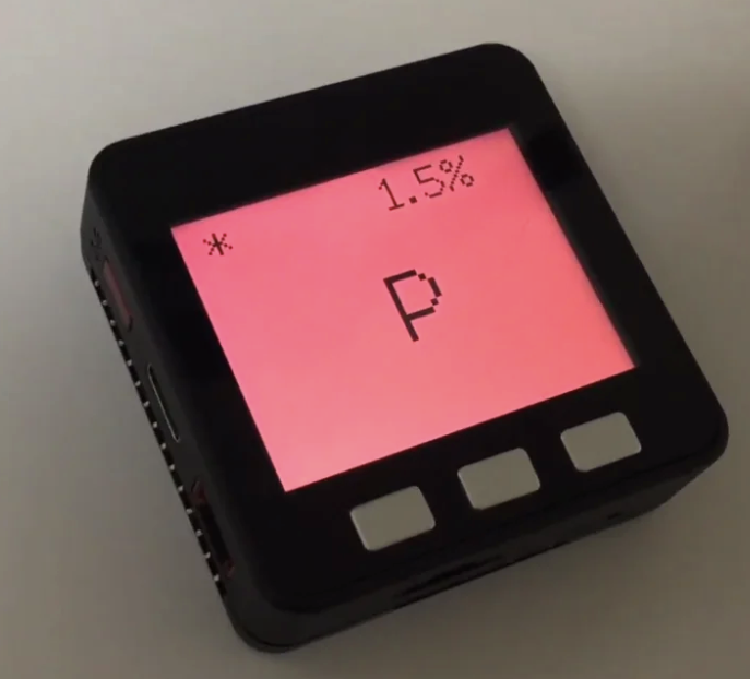
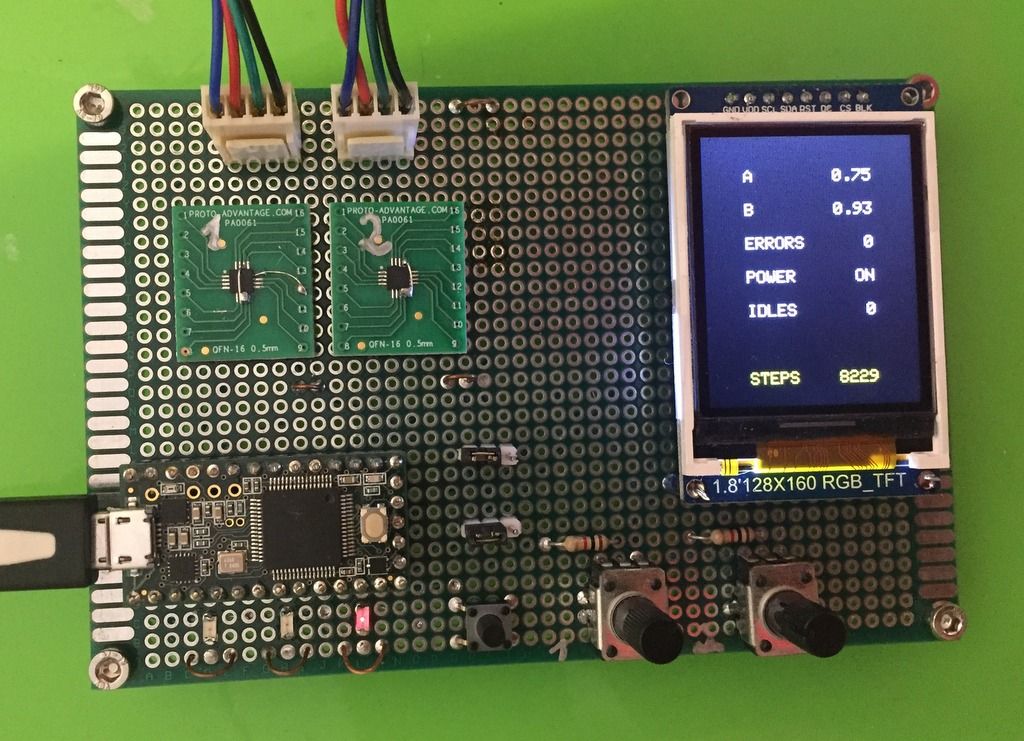
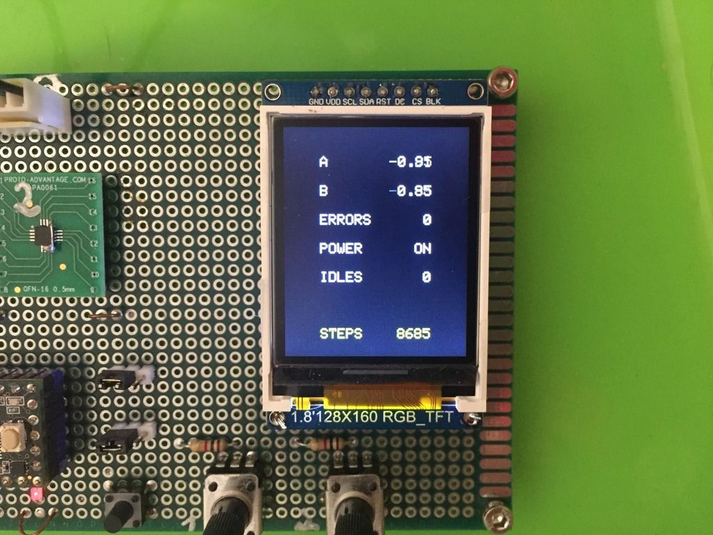
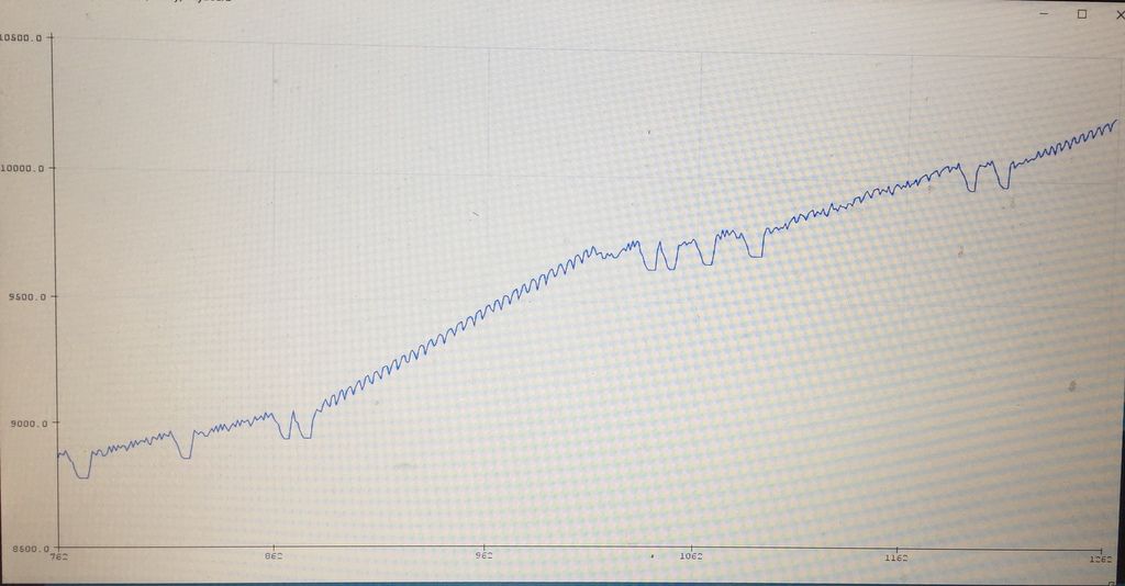
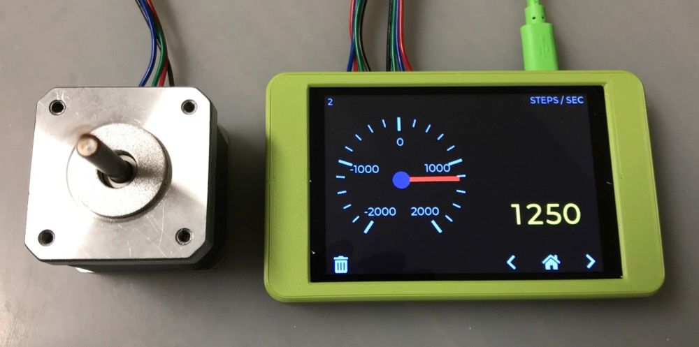
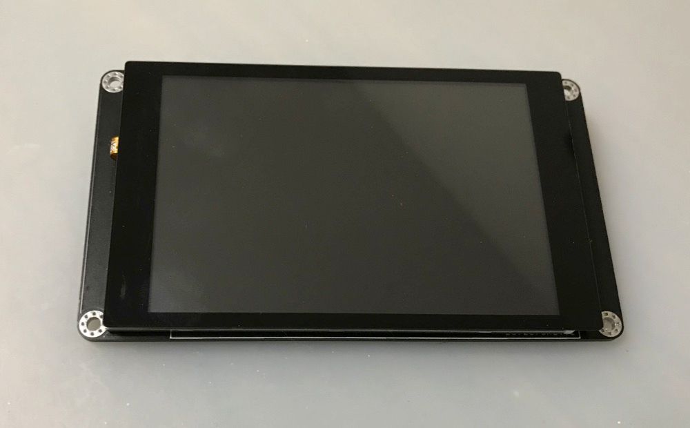
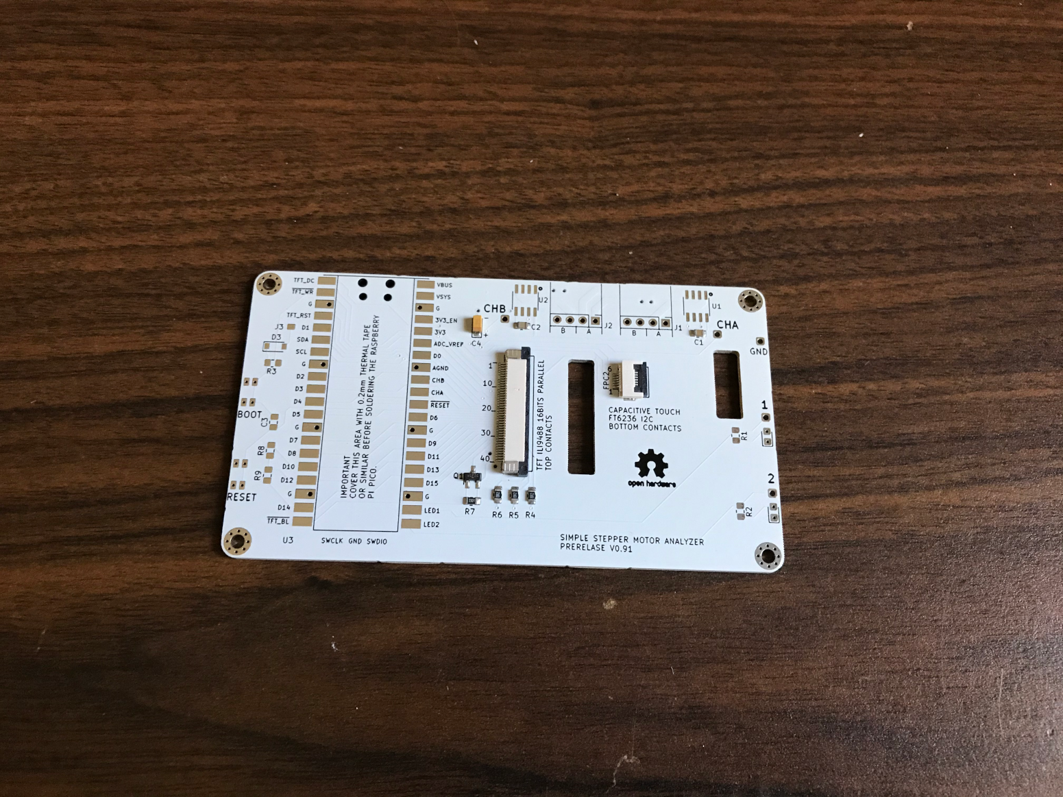
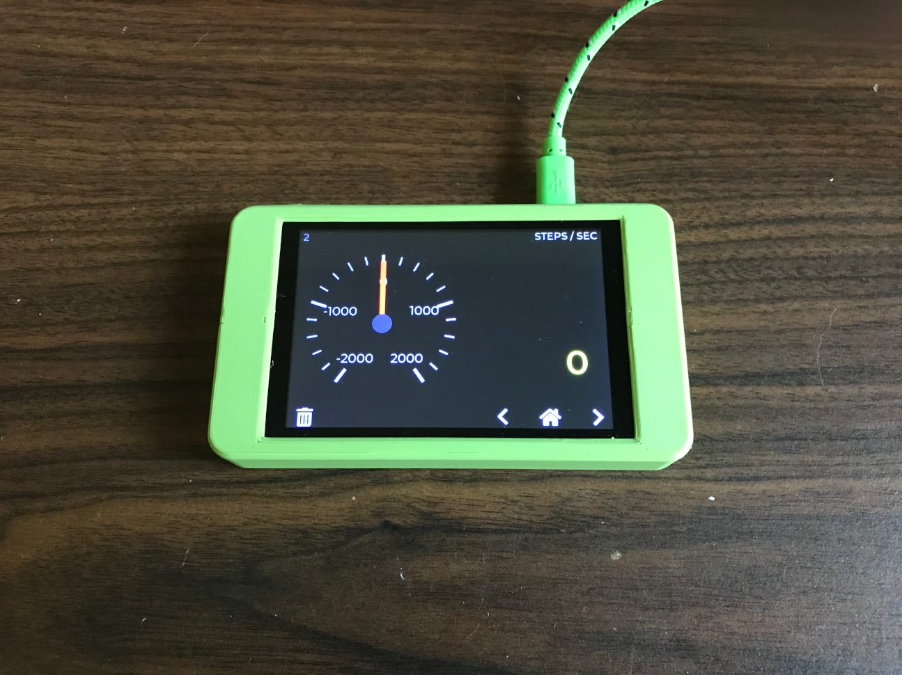
      Since then I worked on and off on a simpler and less expensive design and it works even better. This design uses a 3.5" 'dumb' TFT with a capacitive touch, and ~$3 'blackpill' STM32F401CE board from Ali Express.

      7cc58730-8a51-4d2a-9977-d1bbe4e78533-image.png

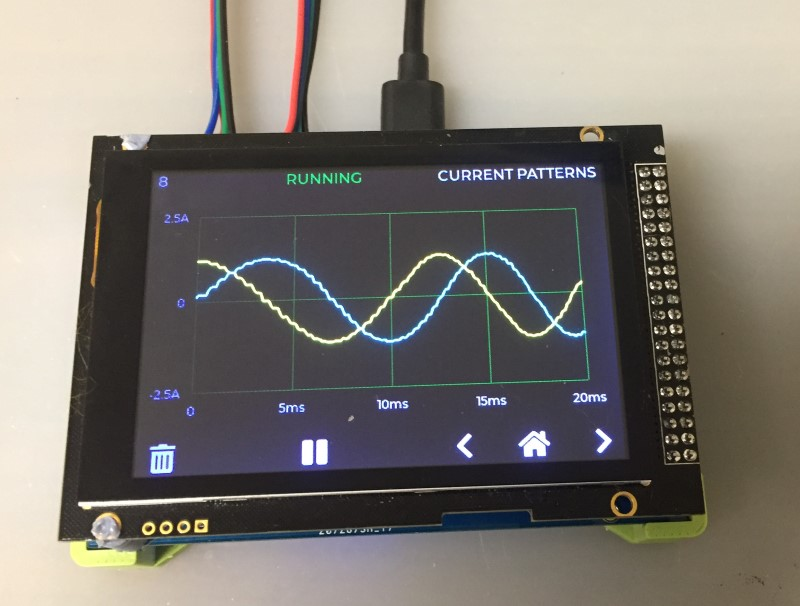
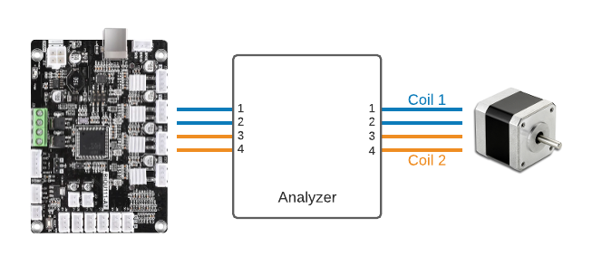
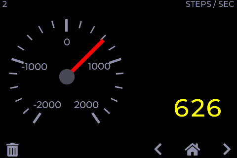
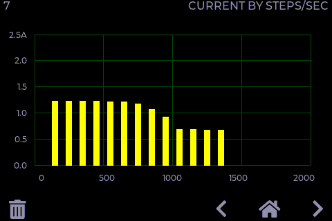
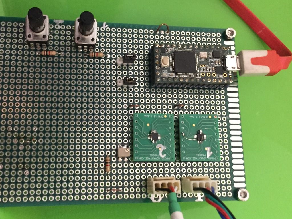
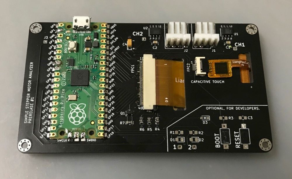
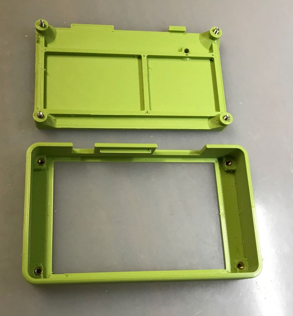
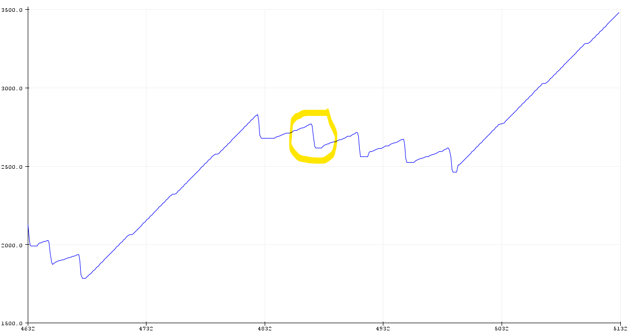
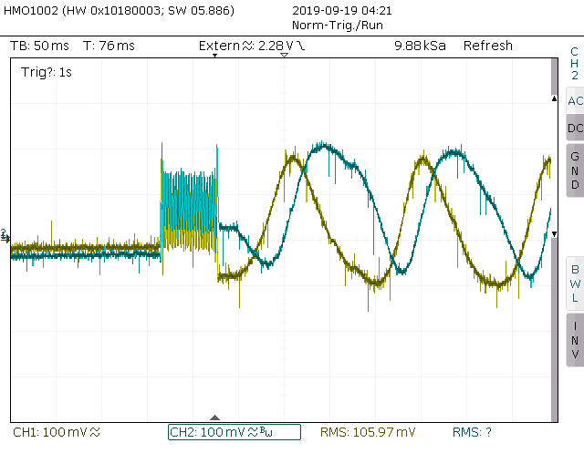
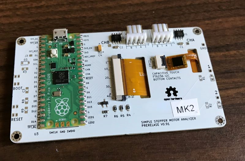
      The hardware design is trivial, with a blackpill module, two small current sensors and a EEPROM to save the settings, and it has a 40pin connector that plugs into the TFT screen. All the heavy lifting, including the signal processing, extraction of stepper measurements and user interface are done by the firmware.

      Github repository and documentation are here https://github.com/zapta/simple_stepper_motor_analyzer and electrical schematic is here https://github.com/zapta/simple_stepper_motor_analyzer/blob/master/kicad/stepper_analyzer-sch.pdf .

      I may be able to make a few available for cost, especially for developers that want to add functionality (C++, Platformio under VSCode, programming/debugging using stlink V2). Flashing of new boards can be done with DFU software over USB, no tools of dongles required).

      If you want to build one, or ten, or a thousand and have questions, I will be happy to answer. The connectors BTW are duet2 compatible. πŸ˜‰

      6dcbcaec-99bc-4f99-b030-dc2ceeeef53e-image.png

      fd29b9fd-e6d4-48a7-a331-4bb8e5ea41cd-image.png

      c410b83c-372f-40b1-9924-66c8f36c4fda-image.png

      posted in General Discussion
      zapta
      zapta
    • RE: Question about the quality of the Duet software..

      @deckingman said in Question about the quality of the Duet software..:

      it means graduates of either Oxford or Cambridge universities.

      Thanks @deckingman. This explains why when I searched for Oxbridge University I got this

      f7a9c02c-a68d-4d27-8aa0-b14af601e154-image.png

      posted in General Discussion
      zapta
      zapta
    • Duet3D Monitor - Adding a big status light to your printer.

      This is an experimental project to have large led indicators with the printer status using data sniffed from the PanelDue serial communication. The pictures below are of the current (second) prototype. It is based on a Teensy LC with an Arduino sketch, an isolated 24/5V DC DC, a small strip of WS2812B RGB leds, and a diodes and a resistor.

      Overall I find it to be very useful. When the printer is busy the light is white which also helps the Wyze webcam at night. Once the print is completed and the extruder cools down to 70C the light changes to green which indicates that it's safe to turn off.

      Programming is done via the Teensy USB connector and the USB cable can be removed in normal operation. I chose the Teensy LC because it provides a good balance between cost, computing power, easy to install and use IDE, and having a 5V output to drive the the WS2812B LEDs. To make the thing working on both the DC/DC and USB power (for development), I cut the VIN/VUSB link at the backside of the teensy and am using two Schottky diodes the OR the 5V from the two sources.

      All the source files are available here: https://github.com/zapta/misc/tree/master/duet3d_monitor . I will add the kicad files one the PCB design is ready.

      0_1559452735534_IMG-1407.JPG

      0_1559452718812_IMG-1408.JPG

      Next I will place everything on a small proper PCB and will replace the cheapo DC/DC with digikey 1951-3441-NDβ€Ž

      0_1559452694660_IMG-1409.JPG

      0_1559452702034_IMG-1410.JPG

      posted in General Discussion
      zapta
      zapta
    • Duet Buddy - a proof of concept remote monitor

      This video shows a proof of concept of a duet WiFi remote monitor. The monitor displays the print progress and changes colors as the duet state changes (in this case from print to pause, cancel and idle).

      https://vimeo.com/388175661

      2020-01-30_00-57-17.png

      At it's current form it's crude but I hope that some creative programmers here can make something more useful and aesthetic.

      The hardware is a fun off the shelf M5Stack Core. It's an ESP32 based Arduino with color screen, battery, charger, buttons, speaker and tons of I/O connectivity. The software polls the duet periodically via WiFi, extract the data it needs and displays it. It is based on the PanelDue json parser and full source code is here https://github.com/zapta/misc/tree/master/duet3d_buddy/arduino https://github.com/richard-mckenna/duet_buddy (repository moved, May 2021)

      The M5Stack has very active community and comes with rich libraries that includes graphics and various widgets that can be useful for a duet monitor. Some graphic demo here https://youtu.be/po3pbBcOxzA?t=404

      posted in General Discussion
      zapta
      zapta
    • Building a DIY public domain low cost stepper motor analyzer

      I am toying with the idea of having a public domain demo design of an inexpensive stepper motor analyzer so others can offer inexpensive kits or finished products, for example for 3D printers builders and tweakers.

      The idea is to sense the current of the stepper motor coils, performa simple analysis in realtime and display useful information and graphs on a small screen (e.g. 1.8" color TFT).

      This is what I have so far, a board with two +/-5A, AC/DC isolated current sensors (ACS70331) and a microcontroller (Teensy 3.2) that make sense of the signals and send the results to a computer via a serial port (the TFT screen is on order, should arrive in a few weeks).

      Currently it decodes accurately full steps but there is sufficient data to interpolate fractions of steps using the current ratios.

      Here is a picture of the prototype board (the two knobs are for testing only, not part of the final design)

      IMG-1671.JPG

      And here is an example graph of extruder steps while printing (0.9deg, 3:1 gear). The large retraction at the end is the end of print retraction.

      Annotation 2019-09-17 210546.png

      Should be easy to compute for example the actual max retraction, that is length of filament that was in the extuder and is now out, due to pressure advance, retraction etc. Other analysis can be for speed, acceleration, RMS current at high speeds and so on).

      posted in General Discussion
      zapta
      zapta
    • RE: Building a DIY public domain low cost stepper motor analyzer

      Had more progress with the analyzer's prototype. It now has a small display and shows information in real time. It shows current in both coils, number of quadrature state errors (e.g. if moving too fast for the stepper), the number of times the stepper was idle and the current step counter. Next I will try to show a graph on the display, of the step counter and/or of the coil currents. May also display aggregated values such as max current, RMS currents, speed, etc.

      The prototype board with the display:
      IMG-1696.JPG

      A close up of the display
      IMG-1698.JPG

      The data the analyzer sends in real time via the USB port is also plotted on the computer. This graph shows the extruder steps while printing Calicat. The big deeps are retractions. The ripples is the the pressure advance (set to 1.5).
      IMG-1699.JPG

      posted in General Discussion
      zapta
      zapta
    • Anybody wants a stepper motor analyzer?

      TL;DR, If you a regular here and would like to purchase a stepper motor analyzer please let me know. I can do a small at-cost run of up to 10 units.

      The Raspberry Pico made headlines a few months ago so I decided to try porting the Simple Stepper Motor analyzer to it, and am happy with the results, so decided to have a small at-cost run of up to 10 units for regulars here that are interested.

      This is a more compact design than the previous one, with a single PCB and components on one side and LCD screen on the other. Capabilities are the same but with possibly smoother display due to the larger RAM and faster CPU.

      The cost per unit is $30 + actual post office fee to ship to your location from the US (It's expensive, can be $30+ to Europe), payment via Amazon gift card (can purchased online) at the time of shipping.

      Note that I don't make any profit, give my time for free, and just hope to be reimbursed for the out of pocket expenses so please adjust your expectations regarding warranty and such πŸ˜‰

      BTW, if you want do built it yourself, including commercially, this design is in the public domain and I hope to release the files and documentation in 2-3 weeks. (electronics, firmware, 3D models and user guide)

      The 3D printed enclosure is not included and you will have to print it yourself. I will try to include the M2.5 threaded inserts.

      IMG-2804.JPG

      IMG-2821.jpg

      IMG-2822.jpg

      IMG-2824.jpg

      posted in General Discussion
      zapta
      zapta
    • RE: Building a DIY public domain low cost stepper motor analyzer

      The analyzer, as primitive as it is now, already helped me diagnose a problem. I often had a general issue of under extrusion so the extruder path was clean and fully functional. Looking at the E steps counter on the analyzer while printing one of the problematic prints, I notices this:

      As you can see, the retraction was significantly longer than the unretraction which results general trend of the filament going OUT of the extruder.
      Annotation 2019-09-18 201652.png

      That also caused errors in the tracking of the stepper steps so it was easy to sync to that point of time with a scope and see this:

      SCR03.PNG

      The unretraction steps are too fast compare to what a that stepper with 24V supply can handle which results in reduced and distorted current patter through the coils.

      Looking at my config.g I found this line which sets the max extruder speed.

      M203 X15000 Y15000 Z3000 E15000

      And reducing it to E1500 solved the problem (the upper limit of reasonable stepper signal on my printer is about E2000). If my calculations are correct this is about 25mm/sec on my extruder with 0.9deg and 3:1 gear reduction.

      Hopefully we will have one day analyzers that will do all this process automatically or even Duet itself since the coil currents are available to it (not sure how though how much information the existing TMC drivers convey to the CPU).

      posted in General Discussion
      zapta
      zapta
    • RE: Anybody wants a stepper motor analyzer?

      Good news, 20 PCBs arrived from JLPCB with some preassembled components. I built one using a screen I had and it seems to work. Now I am waiting for the screen and other components for the first batch of 10 to arrive, should be here within 2-3 weeks. Once this batch is shipped and has no problems, I will work on the next batch.

      As arrived from JLCPCB:
      2de37223-2367-4dae-8719-e81168c85d5c-image.png

      Fully assembled:
      3dfc8bcf-3777-43f7-9661-afb559fafef7-image.png

      Enclosed:
      265fee8a-cf53-486e-b0e2-b0cdf33bf348-image.png

      posted in General Discussion
      zapta
      zapta
    • RE: Anybody wants a stepper motor analyzer?

      A quick update: Still waiting for some components to arrive from china (current sensors, connectors, and Picos). I ordered sensors and connectors with aliexpress-standard-shipping but it's still on the way, same for the Picos from Seeed. Meanwhile I decided to use the waiting time and printed enclosures πŸ˜‰

      b8d396cf-7517-4f12-afd9-a611e332563d-image.png

      posted in General Discussion
      zapta
      zapta

    Latest posts made by zapta

    • RE: [3.4.0rc1] I think the bed heater is overheating?

      @Velvia, I read that this is the recommended way now, but I don't have any experience with it, my heater is attached with that 3M high temp adhesive. I just added RTF along the edges.

      posted in Beta Firmware
      zapta
      zapta
    • RE: ChatGPT Gcode Generator

      I asked ChatGPT how to roast chestnuts and it gave me very nice looking instructions but didn't mention that I need to score the chestnuts with a knife so they don't explode.

      At this point ChatGPT and the likes are amazing, but are still toys. I wouldn't trust them as source of information.

      posted in General Discussion
      zapta
      zapta
    • RE: Simpilfy 3D Send file to printer

      ... and probably every other slicer. πŸ˜‰

      S3D is a dead horse in my opinion. Got a license years ago when it was ahead of the pack and I needed x3g output files but don't see any reason to use it anymore, even for free. YMMV

      posted in General Discussion
      zapta
      zapta
    • RE: Simpilfy 3D Send file to printer

      @dhusolo, FYI, Prusa Slicer works well with Duet and is free.

      posted in General Discussion
      zapta
      zapta
    • RE: New product: Electronic Z motor brake

      @o_lampe , that's an interesting idea.

      Another approach is not to brake the motor or belt but to park the carriage. E.g. it moved to a given height and one or more servo/solenoid activated pins lock it in place.

      BTW, the Voron Switchwire uses this to balance gravity. https://www.amazon.com/KEY-BAK-SUPER48-Retractable-Polycarbonate-Oversized/dp/B0088MQA10

      Edit: from dc42's post above: "RepRapFirmware 3.4 supports motors with brake solenoids, which can be purchased from stepperonline and elsewhere."

      posted in General Discussion
      zapta
      zapta
    • RE: New product: Electronic Z motor brake

      @dc42 , Nero 3D tested the electronic brake with a core XZ printer and it works very well for him. There is only one caveat, it drops down over 10-15 minutes. πŸ˜‰

      https://youtu.be/-39GtYVHS6M?t=866

      Reminds me this experiment https://youtu.be/bP200zhX63Q?t=50

      posted in General Discussion
      zapta
      zapta
    • RE: Are you a mobile or desktop app developer?

      @JoergS5, yes, very much so. Either DWC or any other cross OS client.

      BTW, did you try the python client?

      https://github.com/zapta/ble_stepper_motor_analyzer/tree/main/python

      posted in General Discussion
      zapta
      zapta
    • RE: Are these parts suitable for this 3D printer design?

      Anybody using successfully resume after power cut?

      Never tried it and am not sure how that work, considering the model cooling/heating cycle, and the lack of rehoming.

      I wonder if a UPS would be a more effective solution, to avoid the power cut in the first place, even if just to the steppers if not to the heaters.

      posted in Duet Hardware and wiring
      zapta
      zapta
    • RE: Voron 2.4 build with duet

      @james317, I am using the mini5 + 2 Duet 3 and it works well for me. I have the standard drag chains and wiring with Teflon wires and am happy with it.

      The CAN BUS toolboard may be a good choice but I didn't go with it because of its relatively large size.

      posted in General Discussion
      zapta
      zapta
    • First ever recording of Duet3d 'magic smoke'.

      Ivan is building a giant 3D printer, a very interesting project. Here he connected the SSR's incorrectly which causes the Duet 3 to emits visible smoke, most likely from the power MOSFET.

      https://youtu.be/4QdBHjsvxNs?t=488

      The 'half way rectifiers' he mentions are AC serious diodes that are supposed to cut by half the power or each of the four heaters.

      posted in General Discussion
      zapta
      zapta