Five bar Parallel SCARA print area problem
-
@rutku according to RepRap.cpp source, 9999.9 means: Ideally we would report "unknown" or similar for axis positions that are not known because we haven't homed them, but that requires changes to both DWC and PanelDue.
// So we report 9999.9 instead.[ Maybe I made an error in programming somewhere, that after a G1 H2 move the M114 doesn't know the position. Please go on without the M114 and look whether the hotend position is correct my measuring the distance from the X axis. ] => the C parameter reason is more probable
I see another problem: your C parameter is C-90:90:-90:90
which means the arms 1 and 2 cannot have an angle greater than 90 degree. The Step 3 and 4 tests will not work, because they need bigger angles. Please set the C parameter to C-90:180:-90:180. Even your Step 2 test is at the boundary of the 90 degree limit, maybe this is the reason for the M114 9999.9 values.I plan to rework the firmware for a detailed object model (asking for the paramenters in json format), it would be useful imho to report the reasons for angle limit errors also. It's easy to fall into the angle limit traps.
-
@joergs5 said in Five bar Parallel SCARA print area problem:
which means the arms 1 and 2 cannot have an angle greater than 90 degree. The Step 3 and 4 tests will not work, because they need bigger angles. Please set the C parameter to C-90:180:-90:180. Even your Step 2 test is at the boundary of the 90 degree limit, maybe this is the reason for the M114 9999.9 values.
I did what you said. but gave the same mistake. I wrote 270 degrees, gave the same mistake.
config.g
M669 K9 L1 X-95:93 Y0:0 P126:133 D210:213:0:0 B51:90 A15:165:0:360:0:360 C-90:270:-90:270
M208 X-1000:1000 Y-1000:1000 ; set axis minima and maxima
m114
M114
X:9999.900 Y:9999.900 Z:0.000 E:0.000 E0:0.0 Count 101689 64711 0 Machine 9999.900 9999.900 0.000 Bed comp 0.000
ok
I'm going on by skipping the M114 command.
-
@rutku yes, please skip. I am curious about the results of your tests!
-
@joergs5 said in Five bar Parallel SCARA print area problem:
Step 3 (check for curved line)
homing✓
run G90 G1 H2 X90 F200 and G90 G1 H2 Y90 F200 and verify that both arms are 90 degree and the hotend is on the X0 line✓
run G90 G1 X0 Y100 F200 and verify that arm 1 rotated counterclockwise by about 10 degree and arm 2 rotated clockwise by about 10 degreeThis command is very strange sounds. I repeat the same action four times. The same sound continued to go out.
Strange Sounds
debug
G90 G1 X0 Y100 F200 constraintsOK => cachedInvalid:0 cachedX0:-29.16 cachedY0:307.49 getInverse => not cantilevered proximalL:126.00 distalL:210.00 xOrigL:-95.00 yOrigL:0.00 x_0:0.00 y_0:100.00 getIntersec firstRadius: 126.00 secondRadius: 210.00 firstX: -95.00 firstY: 0.00 secondX: 0.00 secondY: 100.00 getTurn => turn:-16759.64 = (x2:-206.06 - x1:-95.00) * (y3:100.00 - y1:0.00) - (y2:59.51 - y1:0.00) * (x3:0.00 - x1:-95.00) getTurn => turn:16759.64 = (x2:-29.87 - x1:-95.00) * (y3:100.00 - y1:0.00) - (y2:-107.86 - y1:0.00) * (x3:0.00 - x1:-95.00) getTheta => workmode: 1 thetaA:151.82 thetaB:301.12 proxturnA:-16759.64 proxturnB:-16759.64 getTheta => use: 2 x2: -29.87 y2: -107.86 thetaB: 301.12 x1: -206.06 y1: 59.51 thetaA: 151.82 getInverse => not cantilevered proximalR:133.00 distalR:213.00 xOrigR:93.00 yOrigR:0.00 x_0:0.00 y_0:100.00 getIntersec firstRadius: 133.00 secondRadius: 213.00 firstX: 93.00 firstY: 0.00 secondX: 0.00 secondY: 100.00 getTurn => turn:-17592.40 = (x2:21.18 - x1:93.00) * (y3:100.00 - y1:0.00) - (y2:-111.94 - y1:0.00) * (x3:0.00 - x1:93.00) getTurn => turn:17592.40 = (x2:209.85 - x1:93.00) * (y3:100.00 - y1:0.00) - (y2:63.52 - y1:0.00) * (x3:0.00 - x1:93.00) getTheta => workmode: 1 thetaA:237.32 thetaB:28.53 proxturnA:-17592.40 proxturnB:-17592.40 getTheta => use: 2 x2: 209.85 y2: 63.52 thetaB: 28.53 x1: 21.18 y1: -111.94 thetaA: 237.32 getInverse => cachedInvalid 0 cachedX0:0.00 cachedY0:100.00 cachedX1:0.00 cachedY1:100.00 getInverse => cachedXL:-29.87 cachedYL:-107.86 cachedXR:209.85 cachedYR:63.52 cachedThetaR:28.53 cachedXR:209.85 getInverse => cachedYR:63.52 cachedThetaL:301.12 cachedXL:-29.87 cachedYL:-107.86 getInverse => cachedInvalid:0 x_0:0.00 y_0:100.00 xL:-29.87 yL:-107.86 thetaL:301.12 xR:209.85 yR:63.52 thetaR:28.53 x1:0.00 y1:100.00 constraintsOK => cachedInvalid:0 actuatorAngleLMin:-90.00<0 && thetaL:301.12>actuatorAngleLMax:270.00 constraintsOK => thetaL(-58.88) -=360 constraintsOK => cachedInvalid:0 thetaL:-58.88 < actuatorAngleLMin:-90.00 || thetaL:-58.88 > actuatorAngleLMax:270.00 return false constraintsOK => cachedInvalid:0 actuatorAngleRMin:-90.00<0 && thetaR:28.53>actuatorAngleRMax:270.00 constraintsOK => cachedInvalid:0 thetaR:28.53 < actuatorAngleRMin:-90.00 || thetaR:28.53 > actuatorAngleRMax:270.00 return false getAngle => x1:-29.87 y1:-107.86 x2:0.00 y2:100.00 x3:209.85 y3:63.52 getAngle => angle:88.32 = angle2:350.14 - angle1:261.82 constraintsOK => achedInvalid:0 headAngle:88.32 < headAngleMin:15.00 || headAngle:88.32 > headAngleMax:165.00 isnan(headAngle):0 return false getAngle => x1:-95.00 y1:0.00 x2:-29.87 y2:-107.86 x3:0.00 y3:100.00 getAngle => angle:320.70 = 360 + angle2:81.82 - angle1:121.12 constraintsOK => cachedInvalid:0 angleProxDistL:320.70 < proxDistLAngleMin:0.00 || angleProxDistL:320.70 > proxDistLAngleMax:360.00 isnan(angleProxDistL):0 return false getAngle => x1:93.00 y1:0.00 x2:209.85 y2:63.52 x3:0.00 y3:100.00 getAngle => angle:321.61 = 360 + angle2:170.14 - angle1:208.53 constraintsOK => cachedInvalid:0 angleProxDistR:321.61 < proxDistRAngleMin:0.00 || angleProxDistR:321.61 > proxDistRAngleMax:360.00 isnan(angleProxDistR):0 return false constraintsOK => cachedInvalid:0 cachedX0:0.00 cachedY0:100.00 CartesianToMotorSteps => motorPosX = cachedThetaL:301.12 * stespPermm[X_AXIS]924.44 motorPosY = cachedThetaR:28.53 * stepsPermm[Y_AXIS]924.44 CartesianToMotorSteps => machinePos[0]:0.00 machinePos[1]:100.00 motorPosX:0.00 motorPosY:924.44 CartesianToMotorSteps => XYZ_AXES:3 numVisibleAxes:3ok -
@rutku said in Five bar Parallel SCARA print area problem:
88.32 = angle2:350.14
you can try the same test with L2 mode, but I fear, there is an error in the firmware and I have to setup your configuration and test it myself. The debug code looks like the calculated angle is strange and incorrect. Step 3 is exactly where workmode 1 changes to workmode 2, this may confuse the firmware. It should behave logic however even then, leaving the arms at the top. But your debug seems trying to rotate the arms to the bottom.
Please give me your config.g content and the current homing file. Please tell me which firmware version you use. I'll setup a printer like yours. Give me a few days please until thursday.
If you want to further test your printer, use L1 mode and stay in the positive X region with Y between 50 and140. This should work ok. You can make Step 4 test to test whether segmentation is the reason for your curved lines. If you want, you can experiment with the M669 S and T parameter, please see https://duet3d.dozuki.com/Guide/Five+Bar+Parallel+SCARA/24#s103
When I know the reason, I'll tell you which part of the source to change.
-
@joergs5 said in Five bar Parallel SCARA print area problem:
Please give me your config.g content and the current homing file. Please tell me which firmware version you use. I'll setup a printer like yours. Give me a few days please until thursday.
Ok I'm waiting for you. Thank you so much.
m115
FIRMWARE_NAME: RepRapFirmware for STM32F4 based Boards FIRMWARE_VERSION: 3.2.2_2 ELECTRONICS: STM32F4 FIRMWARE_DATE: 2021-05-02
ok
config.g
; General preferences
G90 ; Send absolute coordinates...
M83 ; ...but relative extruder moves
M552 S1 ; Turn network on

M586 P0 S1 ; Enable HTTP
M586 P1 S0 ; Enable FTP
M586 P2 S0 ; Enable Telnet

; Drives
M569 P0 S0 ; Drive 0 (X) goes forwards
M569 P1 S0 ; Drive 1 (Y) goes forwards
;M569 P2 S1 ; Drive 2 (Z) goes forwards
;M569 P3 S1 ; Drive 3 (E0) goes forwards
M584 X0 Y1 ; set drive mapping

M350 X128 Y128 I1 ;S3 ; Configure microstepping with interpolation
M669 K9 L1 X-95:93 Y0:0 P126:133 D210:213:0:0 B51:90 A15:165:0:360:0:360 C-90:270:-90:270
M92 X924.444444 Y924.444444 ; Set steps per mm

M203 X10000 Y10000 ; maximum speeds mm/minute

M566 X15 Y15 ; Set maximum instantaneous speed changes (mm/min)
M201 X40 Y40 ; Set accelerations (mm/s^2)
M906 X1200 Y1200 ; Set motor currents (mA) and motor idle factor in per cent

M84 S0 ; Set idle timeout

; Axis Limits
 M208 X-1000:1000 Y-1000:1000 ; set axis minima and maxima

; Endstops
M574 X1 S1 P"xstop"   ; X min active high endstop switch
M574 Y2 S1 P"ystop"   ; Y min active high endstop switch
;M574 Z0 S1 P"zstop"   ; Z min active high endstop switch
home5barscara.g
G91 ; relative positioning G1 H1 X100 Y300 F400 ; move quickly to endstop and stop there (first pass) G1 H1 X300 F400 G1 H1 Y300 F400 G1 H2 X-2 Y-2 F400 ; go back a few degrees G1 H1 X100 F90 ; move slowly to endstop once more (second pass) G1 H1 Y100 F90 ; move slowly to endstop once more (second pass) ;G1 H2 X-5 Y-5 F400 ; go back a few degrees G92 Z0 G90 ; absolute positioning ;G0 X0 Y90 ; move to a reasonable position -
@rutku thank you.
My idea is to introduce a new mode L5, who joins working modes 1, 3 and 4 to one print area. This would allow you to use most of your area of positive Y.
-
@joergs5 An excellent idea. I was thinking about this idea. I didn't mean to do that without running the system. Also are not required offset for X and Y axes?
-
@rutku the offsets for x and y are required, because the firmware has to know where the actuators are placed.
I will make a new thread in the firmware development space, you'll get a first version for testing when I implemented L5. The thread is here: https://forum.duet3d.com/topic/23483/parallel-scara-printer-improvements
When you and I tested L5 successfully, I'll make a pull request to the official firmware. -
@joergs5 I'm following the topic. I'll be happy to test new updates. Thanks, I'll continue with the other thread.
-
@rutku we should discuss your specific config here, and the firmware development there. I install a printer with the same properties like yours, so we'll find a working solution for your printer.
-
@rutku I thought about merging work modes. This is difficult, because while changing the mode, the position of the hotend changes and during the change and rotations, time is lost. So it must be while not printing and should probably be placed in the slicer, not the firmware. If the firmware decides, it will break the print process at places one doesn't wish.
I concentrate on code verification, i.e. whether the code is correct for work mode 1 for your test scenario (later for the other modes too), and improve the existing code like I describe in the other thread.
-
@joergs5 said in Five bar Parallel SCARA print area problem:
@rutku I thought about merging work modes. This is difficult, because while changing the mode, the position of the hotend changes and during the change and rotations, time is lost. So it must be while not printing and should probably be placed in the slicer, not the firmware. If the firmware decides, it will break the print process at places one doesn't wish.
It doesn't matter. I will think of something in the future. My priority is the work of the 3d printer. After working, I will understand better the codes you wrote.
@joergs5 said in Five bar Parallel SCARA print area problem:
I concentrate on code verification, i.e. whether the code is correct for work mode 1 for your test scenario (later for the other modes too), and improve the existing code like I describe in the other thread.
Yes, I'm looking forward to the result. My 11 month old baby started breaking my 3d printer. I can only debug on my small laptop. My eyes are dying. Tomorrow I will take my 3d printer to my office. I'm going to review your actions on the big monitor in my office. My eyes will be relieved. Have a nice day...

-
@rutku I am currently checking the source
- the source doesn't allow workmode change. When trying angles which are angles of a different work mode, it returns an error
- I'll iterate the angles now and write the secure coordinates you can try
-
@rutku I've found something. In L1 mode, when the angles are negative, the inverse kinematics calculates a high value for the stepper instead of a negative value.
I've inserted a test code. I don't know how you generate your code, but if you compile yourself, you can test: insert the following code into the method getInverse:
the code line before is:
thetaR = righttheta[2];
}
It's the end of the if code block which decides between cantilevered or not.if(thetaL > 270) { thetaL = thetaL - 360; //cout << " corrected thetaL, new value " << thetaL << endl; } if(thetaR > 270) { thetaR = thetaR - 360; //cout << " corrected thetaR, new value " << thetaR << endl; }the code line after is:
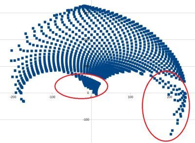
cachedX0 = x_0;I've calculated kinematics and inverse kinematics for angles between -80 and 260 degree and generated a graph in LibreOffice calc for valid values, this is the result (Y axis lines are 100 each). The graph is calculated with angles incrementing 5 degrees each between -80 and +260 degrees. The graph shows positions which are calculated as valid.
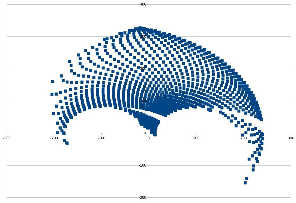
Hopes this helps with testing.
After analyzing firmware, I'll build a printer now. But if you want to test yourself, I wanted you to know my results soon.
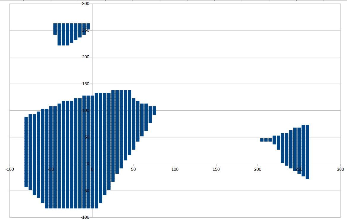
I've made a second graph, X axis is the angle of the first actuator, Y axis of the second. The points are the valid positions of the other graph:
-
config.g
M669 K9 L1 X-95:93 Y0:0 P126:133 D210:213:0:0 B51:90 A15:165:0:360:0:360 C-80:260:-80:260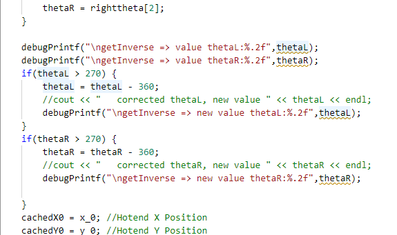
debug
G28

MotorStepsToCartesian => thetaL:220.74=MotorPosX:204064.00/StepsPermmX:924.44
MotorStepsToCartesian => thetaR:220.74=MotorPosY:83200.00/StepsPermmY:924.44
getForwad => getIntersec(distalL:210.00,distalR:213.00,xL:-190.46,yL:-82.23,xR:93.00,yR:133.00)
getIntersec firstRadius: 210.00 secondRadius: 213.00 firstX: -190.46 firstY: -82.23 secondX: 93.00 secondY: 133.00
getTurn => turn:-40677.33 = (x2:-119.27 - x1:-190.46) * (y3:133.00 - y1:-82.23) - (y2:115.33 - y1:-82.23) * (x3:93.00 - x1:-190.46)
getTurn => turn:40677.32 = (x2:18.96 - x1:-190.46) * (y3:133.00 - y1:-82.23) - (y2:-66.72 - y1:-82.23) * (x3:93.00 - x1:-190.46)
getTurn => turn:-13005.09 = (x2:-190.46 - x1:-95.00) * (y3:115.33 - y1:0.00) - (y2:-82.23 - y1:0.00) * (x3:-119.27 - x1:-95.00)
getTurn => turn:28231.32 = (x2:93.00 - x1:93.00) * (y3:115.33 - y1:0.00) - (y2:133.00 - y1:0.00) * (x3:-119.27 - x1:93.00)
getForwad => workmode:1 turnLeft:-13005.09 turnRight:28231.32
MotorStepsToCartesian => MachinePosX:nan MachinePosY:nan XYZ_AXES:3 numVisibleAxes:3
MotorStepsToCartesian => thetaL:51.00=MotorPosX:47147.00/StepsPermmX:924.44
MotorStepsToCartesian => thetaR:51.00=MotorPosY:83200.00/StepsPermmY:924.44
getForwad => getIntersec(distalL:210.00,distalR:213.00,xL:-15.71,yL:97.92,xR:93.00,yR:133.00)
getIntersec firstRadius: 210.00 secondRadius: 213.00 firstX: -15.71 firstY: 97.92 secondX: 93.00 secondY: 133.00
getTurn => turn:-23253.28 = (x2:-29.16 - x1:-15.71) * (y3:133.00 - y1:97.92) - (y2:307.49 - y1:97.92) * (x3:93.00 - x1:-15.71)
getTurn => turn:23253.28 = (x2:95.88 - x1:-15.71) * (y3:133.00 - y1:97.92) - (y2:-79.98 - y1:97.92) * (x3:93.00 - x1:-15.71)
getTurn => turn:17934.62 = (x2:-15.71 - x1:-95.00) * (y3:307.49 - y1:0.00) - (y2:97.92 - y1:0.00) * (x3:-29.16 - x1:-95.00)
getTurn => turn:16246.89 = (x2:93.00 - x1:93.00) * (y3:307.49 - y1:0.00) - (y2:133.00 - y1:0.00) * (x3:-29.16 - x1:93.00)
getForwad => workmode:1 turnLeft:17934.62 turnRight:16246.89
MotorStepsToCartesian => MachinePosX:-29.16 MachinePosY:307.49 XYZ_AXES:3 numVisibleAxes:3
MotorStepsToCartesian => thetaL:49.00=MotorPosX:45298.00/StepsPermmX:924.44
MotorStepsToCartesian => thetaR:49.00=MotorPosY:81351.00/StepsPermmY:924.44
getForwad => getIntersec(distalL:210.00,distalR:213.00,xL:-12.34,yL:95.09,xR:97.64,yR:132.92)
getIntersec firstRadius: 210.00 secondRadius: 213.00 firstX: -12.34 firstY: 95.09 secondX: 97.64 secondY: 132.92
getTurn => turn:-23641.96 = (x2:-28.62 - x1:-12.34) * (y3:132.92 - y1:95.09) - (y2:304.46 - y1:95.09) * (x3:97.64 - x1:-12.34)
getTurn => turn:23641.95 = (x2:103.61 - x1:-12.34) * (y3:132.92 - y1:95.09) - (y2:-80.00 - y1:95.09) * (x3:97.64 - x1:-12.34)
getTurn => turn:18855.43 = (x2:-12.34 - x1:-95.00) * (y3:304.46 - y1:0.00) - (y2:95.09 - y1:0.00) * (x3:-28.62 - x1:-95.00)
getTurn => turn:17578.94 = (x2:97.64 - x1:93.00) * (y3:304.46 - y1:0.00) - (y2:132.92 - y1:0.00) * (x3:-28.62 - x1:93.00)
getForwad => workmode:1 turnLeft:18855.43 turnRight:17578.94
MotorStepsToCartesian => MachinePosX:-28.62 MachinePosY:304.46 XYZ_AXES:3 numVisibleAxes:3
MotorStepsToCartesian => thetaL:51.00=MotorPosX:47147.00/StepsPermmX:924.44
MotorStepsToCartesian => thetaR:51.00=MotorPosY:81351.00/StepsPermmY:924.44
getForwad => getIntersec(distalL:210.00,distalR:213.00,xL:-15.71,yL:97.92,xR:97.64,yR:132.92)
getIntersec firstRadius: 210.00 secondRadius: 213.00 firstX: -15.71 firstY: 97.92 secondX: 97.64 secondY: 132.92
getTurn => turn:-24075.32 = (x2:-24.02 - x1:-15.71) * (y3:132.92 - y1:97.92) - (y2:307.76 - y1:97.92) * (x3:97.64 - x1:-15.71)
getTurn => turn:24075.33 = (x2:95.73 - x1:-15.71) * (y3:132.92 - y1:97.92) - (y2:-80.07 - y1:97.92) * (x3:97.64 - x1:-15.71)
getTurn => turn:17452.44 = (x2:-15.71 - x1:-95.00) * (y3:307.76 - y1:0.00) - (y2:97.92 - y1:0.00) * (x3:-24.02 - x1:-95.00)
getTurn => turn:16982.36 = (x2:97.64 - x1:93.00) * (y3:307.76 - y1:0.00) - (y2:132.92 - y1:0.00) * (x3:-24.02 - x1:93.00)
getForwad => workmode:1 turnLeft:17452.44 turnRight:16982.36
MotorStepsToCartesian => MachinePosX:-24.02 MachinePosY:307.76 XYZ_AXES:3 numVisibleAxes:3
MotorStepsToCartesian => thetaL:51.00=MotorPosX:47147.00/StepsPermmX:924.44
MotorStepsToCartesian => thetaR:51.00=MotorPosY:83200.00/StepsPermmY:924.44
getForwad => getIntersec(distalL:210.00,distalR:213.00,xL:-15.71,yL:97.92,xR:93.00,yR:133.00)
getIntersec firstRadius: 210.00 secondRadius: 213.00 firstX: -15.71 firstY: 97.92 secondX: 93.00 secondY: 133.00
getTurn => turn:-23253.28 = (x2:-29.16 - x1:-15.71) * (y3:133.00 - y1:97.92) - (y2:307.49 - y1:97.92) * (x3:93.00 - x1:-15.71)
getTurn => turn:23253.28 = (x2:95.88 - x1:-15.71) * (y3:133.00 - y1:97.92) - (y2:-79.98 - y1:97.92) * (x3:93.00 - x1:-15.71)
getTurn => turn:17934.62 = (x2:-15.71 - x1:-95.00) * (y3:307.49 - y1:0.00) - (y2:97.92 - y1:0.00) * (x3:-29.16 - x1:-95.00)
getTurn => turn:16246.89 = (x2:93.00 - x1:93.00) * (y3:307.49 - y1:0.00) - (y2:133.00 - y1:0.00) * (x3:-29.16 - x1:93.00)
getForwad => workmode:1 turnLeft:17934.62 turnRight:16246.89
MotorStepsToCartesian => MachinePosX:-29.16 MachinePosY:307.49 XYZ_AXES:3 numVisibleAxes:3
constraintsOK => cachedInvalid:0 cachedX0:0.00 cachedY0:0.00
getInverse => not cantilevered proximalL:126.00 distalL:210.00 xOrigL:-95.00 yOrigL:0.00 x_0:-29.16 y_0:307.49
getIntersec firstRadius: 126.00 secondRadius: 210.00 firstX: -95.00 firstY: 0.00 secondX: -29.16 secondY: 307.49
getTurn => turn:-17934.62 = (x2:-127.24 - x1:-95.00) * (y3:307.49 - y1:0.00) - (y2:121.80 - y1:0.00) * (x3:-29.16 - x1:-95.00)
getTurn => turn:17934.62 = (x2:-15.71 - x1:-95.00) * (y3:307.49 - y1:0.00) - (y2:97.92 - y1:0.00) * (x3:-29.16 - x1:-95.00)
getTheta => workmode: 1 thetaA:104.83 thetaB:51.00 proxturnA:-17934.62 proxturnB:-17934.62
getTheta => use: 2 x2: -15.71 y2: 97.92 thetaB: 51.00 x1: -127.24 y1: 121.80 thetaA: 104.83
getInverse => not cantilevered proximalR:133.00 distalR:213.00 xOrigR:93.00 yOrigR:0.00 x_0:-29.16 y_0:307.49
getIntersec firstRadius: 133.00 secondRadius: 213.00 firstX: 93.00 firstY: 0.00 secondX: -29.16 secondY: 307.49
getTurn => turn:-16246.89 = (x2:1.73 - x1:93.00) * (y3:307.49 - y1:0.00) - (y2:96.74 - y1:0.00) * (x3:-29.16 - x1:93.00)
getTurn => turn:16246.89 = (x2:93.00 - x1:93.00) * (y3:307.49 - y1:0.00) - (y2:133.00 - y1:0.00) * (x3:-29.16 - x1:93.00)
getTheta => workmode: 1 thetaA:133.33 thetaB:90.00 proxturnA:-16246.89 proxturnB:-16246.89
getTheta => use: 2 x2: 93.00 y2: 133.00 thetaB: 90.00 x1: 1.73 y1: 96.74 thetaA: 133.33
getInverse => value thetaL:51.00
getInverse => value thetaR:90.00
getInverse => cachedInvalid 0 cachedX0:-29.16 cachedY0:307.49 cachedX1:-29.16 cachedY1:307.49
getInverse => cachedXL:-15.71 cachedYL:97.92 cachedXR:93.00 cachedYR:133.00 cachedThetaR:90.00 cachedXR:93.00
getInverse => cachedYR:133.00 cachedThetaL:51.00 cachedXL:-15.71 cachedYL:97.92
getInverse => cachedInvalid:0 x_0:-29.16 y_0:307.49 xL:-15.71 yL:97.92 thetaL:51.00 xR:93.00 yR:133.00 thetaR:90.00 x1:-29.16 y1:307.49
constraintsOK => cachedInvalid:0 actuatorAngleLMin:-80.00<0 && thetaL:51.00>actuatorAngleLMax:260.00
constraintsOK => cachedInvalid:0 thetaL:51.00 < actuatorAngleLMin:-80.00 || thetaL:51.00 > actuatorAngleLMax:260.00 return false
constraintsOK => cachedInvalid:0 actuatorAngleRMin:-80.00<0 && thetaR:90.00>actuatorAngleRMax:260.00
constraintsOK => cachedInvalid:0 thetaR:90.00 < actuatorAngleRMin:-80.00 || thetaR:90.00 > actuatorAngleRMax:260.00 return false
getAngle => x1:-15.71 y1:97.92 x2:-29.16 y2:307.49 x3:93.00 y3:133.00
getAngle => angle:31.32 = angle2:305.00 - angle1:273.67
constraintsOK => achedInvalid:0 headAngle:31.32 < headAngleMin:15.00 || headAngle:31.32 > headAngleMax:165.00 isnan(headAngle):0 return false
getAngle => x1:-95.00 y1:0.00 x2:-15.71 y2:97.92 x3:-29.16 y3:307.49
getAngle => angle:222.67 = 360 + angle2:93.67 - angle1:231.00
constraintsOK => cachedInvalid:0 angleProxDistL:222.67 < proxDistLAngleMin:0.00 || angleProxDistL:222.67 > proxDistLAngleMax:360.00 isnan(angleProxDistL):0 return false
getAngle => x1:93.00 y1:0.00 x2:93.00 y2:133.00 x3:-29.16 y3:307.49
getAngle => angle:215.00 = 360 + angle2:125.00 - angle1:270.00
constraintsOK => cachedInvalid:0 angleProxDistR:215.00 < proxDistRAngleMin:0.00 || angleProxDistR:215.00 > proxDistRAngleMax:360.00 isnan(angleProxDistR):0 return false
constraintsOK => cachedInvalid:0 cachedX0:-29.16 cachedY0:307.49
CartesianToMotorSteps => motorPosX = cachedThetaL:51.00 * stespPermm[X_AXIS]924.44
 motorPosY = cachedThetaR:90.00 * stepsPermm[Y_AXIS]924.44
CartesianToMotorSteps => machinePos[0]:-29.16 machinePos[1]:307.49 motorPosX:0.00 motorPosY:924.44
CartesianToMotorSteps => XYZ_AXES:3 numVisibleAxes:3
constraintsOK => cachedInvalid:0 cachedX0:-29.16 cachedY0:307.49
CartesianToMotorSteps => motorPosX = cachedThetaL:51.00 * stespPermm[X_AXIS]924.44
 motorPosY = cachedThetaR:90.00 * stepsPermm[Y_AXIS]924.44
CartesianToMotorSteps => machinePos[0]:-29.16 machinePos[1]:307.49 motorPosX:0.00 motorPosY:924.44
CartesianToMotorSteps => XYZ_AXES:3 numVisibleAxes:3ok
WiFi module is connected to access point Utku, IP address 192.168.1.12
M114
X:-29.157 Y:307.490 Z:0.000 E:0.000 E0:0.0 Count 47147 83200 0 Machine -29.157 307.490 0.000 Bed comp 0.000
ok
G90 G1 H2 Y90 F200
ok
G90 G1 H2 X90 F200

MotorStepsToCartesian => thetaL:90.00=MotorPosX:83200.00/StepsPermmX:924.44
MotorStepsToCartesian => thetaR:90.00=MotorPosY:83200.00/StepsPermmY:924.44
getForwad => getIntersec(distalL:210.00,distalR:213.00,xL:-95.00,yL:126.00,xR:93.00,yR:133.00)
getIntersec firstRadius: 210.00 secondRadius: 213.00 firstX: -95.00 firstY: 126.00 secondX: 93.00 secondY: 133.00
getTurn => turn:-35633.12 = (x2:-11.42 - x1:-95.00) * (y3:133.00 - y1:126.00) - (y2:318.65 - y1:126.00) * (x3:93.00 - x1:-95.00)
getTurn => turn:35633.12 = (x2:2.68 - x1:-95.00) * (y3:133.00 - y1:126.00) - (y2:-59.90 - y1:126.00) * (x3:93.00 - x1:-95.00)
getTurn => turn:-10531.36 = (x2:-95.00 - x1:-95.00) * (y3:318.65 - y1:0.00) - (y2:126.00 - y1:0.00) * (x3:-11.42 - x1:-95.00)
getTurn => turn:13887.57 = (x2:93.00 - x1:93.00) * (y3:318.65 - y1:0.00) - (y2:133.00 - y1:0.00) * (x3:-11.42 - x1:93.00)
getForwad => workmode:1 turnLeft:-10531.36 turnRight:13887.57
MotorStepsToCartesian => MachinePosX:nan MachinePosY:nan XYZ_AXES:3 numVisibleAxes:3ok

MotorStepsToCartesian => thetaL:90.00=MotorPosX:83200.00/StepsPermmX:924.44
MotorStepsToCartesian => thetaR:90.00=MotorPosY:83200.00/StepsPermmY:924.44
getForwad => getIntersec(distalL:210.00,distalR:213.00,xL:-95.00,yL:126.00,xR:93.00,yR:133.00)
getIntersec firstRadius: 210.00 secondRadius: 213.00 firstX: -95.00 firstY: 126.00 secondX: 93.00 secondY: 133.00
getTurn => turn:-35633.12 = (x2:-11.42 - x1:-95.00) * (y3:133.00 - y1:126.00) - (y2:318.65 - y1:126.00) * (x3:93.00 - x1:-95.00)
getTurn => turn:35633.12 = (x2:2.68 - x1:-95.00) * (y3:133.00 - y1:126.00) - (y2:-59.90 - y1:126.00) * (x3:93.00 - x1:-95.00)
getTurn => turn:-10531.36 = (x2:-95.00 - x1:-95.00) * (y3:318.65 - y1:0.00) - (y2:126.00 - y1:0.00) * (x3:-11.42 - x1:-95.00)
getTurn => turn:13887.57 = (x2:93.00 - x1:93.00) * (y3:318.65 - y1:0.00) - (y2:133.00 - y1:0.00) * (x3:-11.42 - x1:93.00)
getForwad => workmode:1 turnLeft:-10531.36 turnRight:13887.57
MotorStepsToCartesian => MachinePosX:nan MachinePosY:nan XYZ_AXES:3 numVisibleAxes:3
Unfortunately something has not changed. Still in an unknown area.
-
@rutku said in Five bar Parallel SCARA print area problem:
G90 G1 H2 Y90 F200 ok G90 G1 H2 X90 F200
this is not correct, because it is working mode 2, and you start with working mode 1 (the homing position). My test proposal was not correct. After looking at the working modes in more detail, I am aware that the working mode change is not possible and my test szenario doesn't work. It has only some value to check whether rotation direction and M92 values are correct.
You can rotate with G1 H2 everywhere you want, but you're leaving the correct working mode in this case and the code says not reachable in any case where the angle positions don't match the working mode. This is checked in getForwared in the section
	// Sanity check the elbow joins to make sure it's in the correct work mode
	const float tL = getTurn(xOrigL, yOrigL, xL, yL, xDst, yDst);
	const float tR = getTurn(xOrigR, yOrigR, xR, yR, xDst, yDst);

	if ((workmode == 1 && (tL < 0 || tR < 0)) ||
		(workmode == 2 && (tL > 0 || tR < 0)) ||
		(workmode == 3 && (tL < 0 || tR > 0)) ||
		(workmode == 4 && (tL > 0 || tR > 0)))
	{
		xDst = std::numeric_limits<float>::quiet_NaN();
		yDst = std::numeric_limits<float>::quiet_NaN();
	}
It sets the result to nan if the angles are not correct. In this case the actuator 1 has the elbow of workmode 2 which means the G1 H2 has cheated changing the working mode. Technically the first actuator was going through singularity type 2 and changed mode. As a normal G1 there would be an error and the move forbidden, but G1 H2 allows all moves. I've made a step 16 in documentation to explain it.
Please make normal G1 moves after homing inside the area which is in the first graph.
-
@rutku I changed the code fix to a general approach. Deciding whether the angle of the inverse kinematics is at the boundaries of the C parameter of M669, so I used those as decision point now:
if(thetaL > actuatorAngleLMax) {
	thetaL -= 360;
}
if(thetaL < actuatorAngleLMin) {
	thetaL += 360;
}
if(thetaR > actuatorAngleRMax) {
	thetaR -= 360;
}
if(thetaR < actuatorAngleRMin) {
	thetaR += 360;
}
This code is verified for L1. I have to check L2, L3, L4.
-
@rutku I was curious about the second graph's two small areas at top and at left - which cartesian coordinates result in those strange angles? The result:
The small area on top results in:
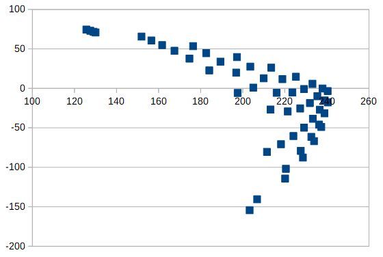
The small area on the right results in:
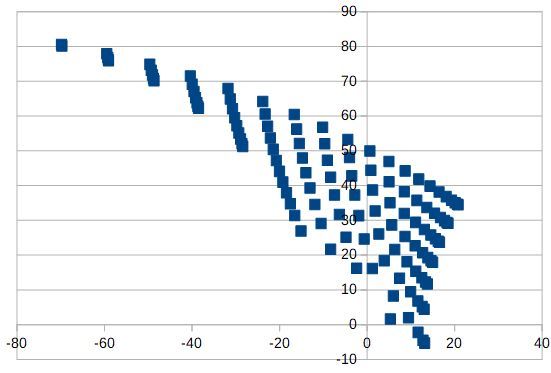
I.e. they are those areas:
-
@joergs5 I plotted the square about right. How to Calibration from this process step? There are spaces in the part of the pen. I will fix them and do drawing again.
square.gcode
G90
G1 X0 Y150
G1 X0 Y200
G1 X50 Y200
G1 X50 Y150
G1 X0 Y150

