Five bar Parallel SCARA print area problem
-
@joergs5 I plotted the square about right. How to Calibration from this process step? There are spaces in the part of the pen. I will fix them and do drawing again.
square.gcode
G90
G1 X0 Y150
G1 X0 Y200
G1 X50 Y200
G1 X50 Y150
G1 X0 Y150


-
@joergs5 I have changed the way you say. I have achieved the square shape after changing the direction of the arms. I guess codes don't have hard trouble. It remains to arrange the print area.

-
-
@rutku For L2 mode (but you need a different homing position for testing this, e.g. 90 and 90 degrees) the result of the hotend coordinates is:

and the angles:

The fix works for this mode also.
-
@joergs5 Nice development. X and Y axis No access to points 0. How do I do offset?
-
@rutku your square test looks much better now!
The imperfection is IMHO due to reasons like swinging arms, hinge backlash (play which has negative results if you change direction) and similar reasons.
You can try to improve by making your test with low speed, e.g. all movements with F10 parameter. This is very slow, but should improve the result. Improving the hinges is possible by pressing the hinge to one side of the hinge with e.g. a spring with low pressure.
The somewhat wobbly line will be due to the resistance of the pen on the surface, a kind of slip stick effect. A felt-tip pen on foil will probably work better, or using fine grained paper.
-
@rutku 0,0 is not accessible due to singularity (distal arms are in opposite, straight line), this is not solvable. You can change offset by setting the X and Y coordinates of the actuators to other values (eg instead of X -95,95 set to 5,195), but this doesn't help, the singularity remains (is then at X100,Y0). Singularity are unprintable areas.
-
@rutku one hint I wanted to add: when you approach singularity areas, you will often experience that the stepper has more work to do. This may lead to lost steps, you may hear the sound of it. Result is, the firmware and actual position of the steppers doesn't fit any more. You must run homing again to set the positions right then. Lost steps often result in layer shifts, but in case of Scara the algorithm will be at the wrong place and the result wrong additionally.
-
@joergs5 said in Five bar Parallel SCARA print area problem:
The imperfection is IMHO due to reasons like swinging arms, hinge backlash (play which has negative results if you change direction) and similar reasons.
Yes, I will include the bearing on the hinges. The friction will be on the bearing.
The somewhat wobbly line will be due to the resistance of the pen on the surface, a kind of slip stick effect. A felt-tip pen on foil will probably work better, or using fine grained paper.
I want to place hotend. I want to fix it with 3D prints.
0,0 is not accessible due to singularity (distal arms are in opposite, straight line), this is not solvable. You can change offset by setting the X and Y coordinates of the actuators to other values (eg instead of X -95,95 set to 5,195), but this doesn't help, the singularity remains (is then at X100,Y0). Singularity are unprintable areas.
So how are we going to escape this singularity? How do we create a square or circle printing area?
one hint I wanted to add: when you approach singularity areas, you will often experience that the stepper has more work to do. This may lead to lost steps, you may hear the sound of it. Result is, the firmware and actual position of the steppers doesn't fit any more. You must run homing again to set the positions right then. Lost steps often result in layer shifts, but in case of Scara the algorithm will be at the wrong place and the result wrong additionally.
Is it logical to use the closed loop stepper? I took my printer to the office. I will review the codes you are writing. I will try to add things.
-
@rutku said in Five bar Parallel SCARA print area problem:
So how are we going to escape this singularity? How do we create a square or circle printing area?
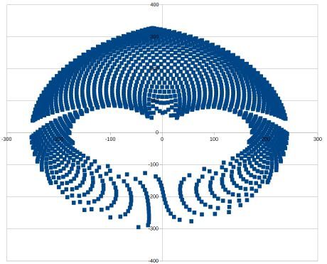
The singularity cannot be escaped, you can select a printing area in the blue area of the first graph, e.g. you could select X from -100 to 100 and Y from 100 to 200. Or if you want to print a square object, X from -80 to 80 and Y from 100 to about 250. A very long object could be from X from -200 to 200 and Y from 100 to 150. A circle printing area could be a circle around the center X0Y200.
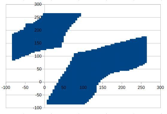
I would avoid including the two special areas which I analyzed separately, because moving there means a massive angle change, which will result in high required time and probably results in printing problems. Therefore I would limit angle 1 to below 100 and angle 2 below 150.
(all those values are for your specific configuration of actuator distance and arm lengths)
Is it logical to use the closed loop stepper?
My personal opinion, the views are somewhat controversial:
a closed loop doesn't help, it only detects lost steps better. But if you don't have a very clever recover solution, you'll have a lost print whether you use closed loop or not. Steppers without closed loops are very reliable, if you don't overload them (like near a singularity with high load, or too high microsteps with too high processing load so that the stepper doesn't receive all steps). You can check steppers by homing before every layer. This was discussed in this forum in a thread, but it requires additional print time. A discussion with different opinions was here: https://forum.duet3d.com/topic/15139/layer-shift-detection Although main focus is stepper vs servo, there is some information about closed loop and homing at every layer shift also.