Duet3D Logo Duet3D
    • Tags
    • Documentation
    • Order
    • Register
    • Login

    Understanding Height Maps

    Scheduled Pinned Locked Moved
    Tuning and tweaking
    4
    48
    2.4k
    Loading More Posts
    • Oldest to Newest
    • Newest to Oldest
    • Most Votes
    Reply
    • Reply as topic
    Log in to reply
    This topic has been deleted. Only users with topic management privileges can see it.
    • jsinicroundefined
      jsinicro @jsinicro
      last edited by

      @jsinicro OK, so the M671 to define the lead screws of the Z axis, is this dimension from the nozzle to the lead screws? OK so this is not from the springs bed manual level wheel screws? This is from the motor lead screws to the nozzle?

      jsinicroundefined 1 Reply Last reply Reply Quote 0
      • jsinicroundefined
        jsinicro @jsinicro
        last edited by

        @jsinicro OK my question is what are the "You must use the M671 command to define the X and Y coordinates of the adjusting screws"?

        fcwiltundefined 1 Reply Last reply Reply Quote 0
        • fcwiltundefined
          fcwilt @jsinicro
          last edited by

          @jsinicro said in Understanding Height Maps:

          @jsinicro OK my question is what are the "You must use the M671 command to define the X and Y coordinates of the adjusting screws"?

          Assuming a single tool setup when the printer is properly homed a G1 X0 Y0 command moves the nozzle to X=0 Y=0.

          They X and Y coordinates of the lead screws/adjusting screws are in reference to that point X=0 Y=0.

          Frederick

          Printers: a small Utilmaker style, a small CoreXY and a E3D MS/TC setup. Various hotends. Using Duet 3 hardware running 3.4.6

          jsinicroundefined 2 Replies Last reply Reply Quote 0
          • jsinicroundefined
            jsinicro @fcwilt
            last edited by

            @fcwilt OK, I have not yet figured out how to measure the lead screws distance to some what reference point to satisfy the M671 command?

            I ran the Hight leveling routine again and the results are after I made sure that the X axis is parallel with the bed here are the results:
            26a9f7b6-85c9-4745-92e8-5e7f4c6e8e08-image.png

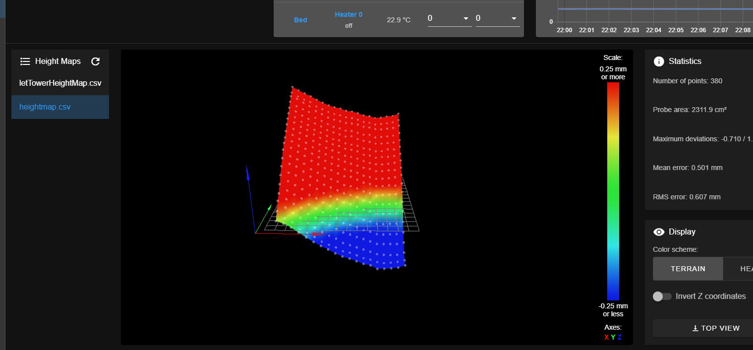
            they are pretty much the same.

            1 Reply Last reply Reply Quote 0
            • jsinicroundefined
              jsinicro @fcwilt
              last edited by

              @fcwilt OK, not sure what you mean by "lead screws/adjusting screws" lead screws are different from adjusting screws right. The lead screw is the screw that the motor turns -in this case the Z axis right?

              jsinicroundefined fcwiltundefined 2 Replies Last reply Reply Quote 0
              • jsinicroundefined
                jsinicro @jsinicro
                last edited by

                @jsinicro here is a picture of the printer, the two wooden pieces are of the exact height and were used to measure and adjust the lead screw to the same height at both ends of the X axis, the I ran the height map routine.
                IMG_2286.jpg

                1 Reply Last reply Reply Quote 0
                • Phaedruxundefined
                  Phaedrux Moderator
                  last edited by

                  Have you seen this?

                  https://duet3d.dozuki.com/Wiki/Bed_levelling_using_multiple_independent_Z_motors

                  Z-Bot CoreXY Build | Thingiverse Profile

                  1 Reply Last reply Reply Quote 0
                  • fcwiltundefined
                    fcwilt @jsinicro
                    last edited by fcwilt

                    @jsinicro said in Understanding Height Maps:

                    @fcwilt OK, not sure what you mean by "lead screws/adjusting screws" lead screws are different from adjusting screws right. The lead screw is the screw that the motor turns -in this case the Z axis right?

                    The firmware supports auto bed leveling and manual bed leveling.

                    Auto bed leveling requires multiple Z steppers.

                    Manual bed leveling can make use of "thumb screws" that you turn by hand to make the needed adjustments to level the bed.

                    Now as to determining the X and Y coordinates to enter with the M671 command.

                    Consider this image of a imaginary printer bed arrangement:

                    Grid Setup.jpg

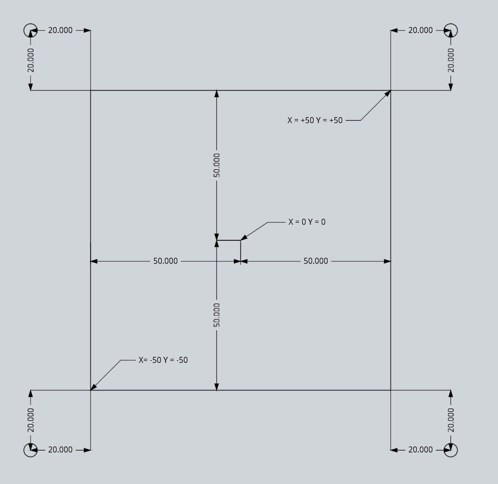
                    The M208 command would be M208 X-50:50 Y-50:50 which means the printable area is 100 x 100 and X=0 Y=0 is at the center of the bed.

                    The four lead screws are 20 x 20 off each corner.

                    Lets assume that the Z steppers are assigned in the M584 command in this order:

                    • left front
                    • left rear
                    • right rear
                    • right front

                    So for the M671 we must specify the lead screw positions in the same order:

                    • left front
                    • left rear
                    • right rear
                    • right front

                    So that gives us M671 X-70:-70:70:70 Y:-70:70:70:-70

                    All the measurements are taken from the X=0 Y=0 point at the center of the bed.

                    Does that make it clear?

                    Printers: a small Utilmaker style, a small CoreXY and a E3D MS/TC setup. Various hotends. Using Duet 3 hardware running 3.4.6

                    jsinicroundefined 1 Reply Last reply Reply Quote 1
                    • jsinicroundefined
                      jsinicro @fcwilt
                      last edited by

                      @fcwilt Yes, that's awesome thankyou. I will comeback this evening to do this.

                      jsinicroundefined 1 Reply Last reply Reply Quote 0
                      • jsinicroundefined
                        jsinicro @jsinicro
                        last edited by

                        @jsinicro OK so I think I understand the auto probing, I've set up the bed.g with 5 points 4 corners and the the center of the bed. should I execute the G29 to enable compensation at the end after the probing?

                        1 Reply Last reply Reply Quote 0
                        • jsinicroundefined
                          jsinicro
                          last edited by

                          @jsinicro OK, so this is the new bed.g:

                          ; bed.g
                          ; called to perform automatic bed compensation via G32
                          ;
                          ; generated by RepRapFirmware Configuration Tool v3.2.3 on Sun Apr 18 2021 23:08:09 GMT-0400 (Eastern Daylight Time)
                          M561 ; clear any bed transform
                          
                          G30 K0 P0 X0 Y0 Z-9999
                          G30 K0 P1 X0 Y500 Z-9999
                          G30 K0 P2 X500 Y500 Z-9999
                          G30 K0 P3 X500 Y50 Z-9999
                          G30 K0 P4 X300 Y300 Z-9999
                          
                          undefined
                          

                          However when I execute this it runs into the X endstop eventually it stops don't understand why I home all first then in the home all after the homez I put the G32 command. Why is it running into the endstop?

                          fcwiltundefined 1 Reply Last reply Reply Quote 0
                          • fcwiltundefined
                            fcwilt @jsinicro
                            last edited by

                            @jsinicro

                            Hi,

                            Please post your most recent config.g file.

                            Thanks.

                            Frederick

                            Printers: a small Utilmaker style, a small CoreXY and a E3D MS/TC setup. Various hotends. Using Duet 3 hardware running 3.4.6

                            jsinicroundefined 1 Reply Last reply Reply Quote 0
                            • jsinicroundefined
                              jsinicro @fcwilt
                              last edited by

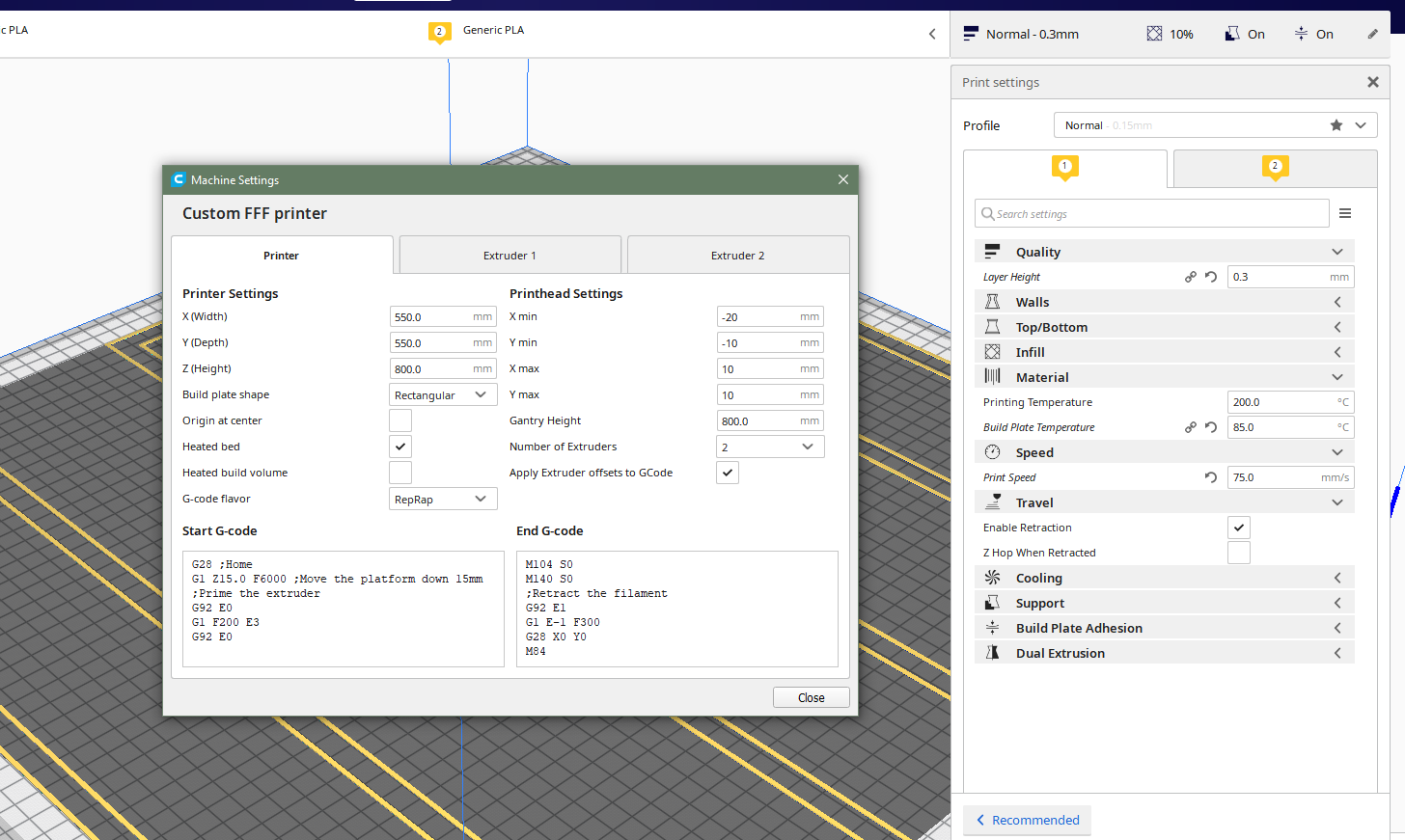
                              @fcwilt here's my current config.g, also I tried a test print including the one Phaedrux posted above the bedlevel_nozzle stl file I used Cura the latest version and used the default settings to slice it. The print started but it was sitting there at the beginning not doing anything, but the web interface was showing that it was processing the print -time percentage was incrreasing, did not get any errors.

                              I then used a previous print and it seems that the nozzle keeps going too close to the bed even after I used a G92 Z0 to set a new position -moved the nozzle up and then used the G92 cmd.

                              FYI I decided to put the M999 at the end of the config file so that it would reset my U axis travel direction automatically however that's not something to do as then once printer turned back on I could no longer establish a network connection so this has been removed.

                              ; Configuration file for Duet 3 (firmware version 3)
                              ; executed by the firmware on start-up
                              ;
                              ; generated by RepRapFirmware Configuration Tool v3.2.3 on Sun Apr 18 2021 23:08:09 GMT-0400 (Eastern Daylight Time)
                              
                              ; General preferences
                              G90                                             ; send absolute coordinates...
                              M83                                             ; ...but relative extruder moves
                              M550 P"jsinicro_1"                              ; set printer name
                              
                              ; Network
                              M551 P"tinisa1125"                              ; set password
                              M552 P0.0.0.0 S1                                ; enable network and acquire dynamic address via DHCP
                              M586 P0 S1                                      ; enable HTTP
                              M586 P1 S0                                      ; disable FTP
                              M586 P2 S0                                      ; disable Telnet


                              ; Set Kinematics type and kinematics parameters
                              M669 K0                                         ;X1:0:0 Y0:1:0 Z0:0:1 U1:0:0
                              ;
                              ; Drives S = motor direction 0 is backwards/reversed direction based on motor orientation
                              ;
                              M569 P0.0 S1                                    ; physical drive 0.0 goes forwards z xxis 1 motor 1
                              M569 P0.1 S1                                    ; physical drive 0.1 goes forwards z axis 2 motor 1
                              M569 P0.2 S1                                    ; physical drive 0.2 goes forwards y axis 1 motor 1
                              M569 P0.3 S1                                    ; physical drive 0.3 goes forwards y axis 1 motor 2
                              M569 P0.4 S1                                    ; physical drive 0.4 goes forwards z axis 2 motor 2
                              M569 P0.5 S1                                    ; physical drive 0.5 goes forwards z axis 1 motor 2
                              M569 P1.0 S1                                    ; physical drive 1.0 goes forwards x axis 2 motor 1
                              M569 P1.1 S0                                    ; physical drive 1.1 goes forwards x axis 2 tool 1 motor
                              M569 P3.0 S0                                    ; physical drive 3.0 goes forwards x axis 1 motor 1 
                              M569 P3.1 S0                                    ; physical drive 3.1 goes forwards x axis 1 tool 2 motor
                              
                              ; mapping 2 motors on separate X axis and 2 motors each on 2 separate Z axis Y has just 2 motors
                              ;M584 R0 S0 X1.0 U3.0 Y0.2:0.3 Z0.0:0.5:0.1:0.4 E1.1:3.1 P4
                              M584 R0 S0 X1.0 U3.0 Y0.2:0.3 Z0.0:0.5:0.1:0.4 E1.1:3.1 P4
                              
                              M350 X16 Y16 Z16 U16 E16:16 I1                           ; configure microstepping with interpolation
                              M92 X80.00 Y395.72 Z400.00 U80.00 E840.99:840.99          ; set steps per mm
                              M566 X300.00 Y300.00 Z60.00 U300.00 E120.00:120.00            ; set maximum instantaneous speed changes (mm/min)
                              M203 X900.00 Y900.00 Z180.00 U900.00 E900.00:900.00      ; set maximum speeds (mm/min)
                              M201 X150.00 Y200.00 Z20.00 U150.00 E150.00:150.00            ; set accelerations (mm/s^2)
                              M906 X800 Y1200 Z1200 U800 E800:800 I30                           ; set motor currents (mA) and motor idle factor in per cent
                              M84 S30                                                         ; Set idle timeout
                              
                              M671 X139.21:-120.26:139.21:-120.26 Y-101:-101:-101:-101    ; lead screws offsets from X0,Y0 homed nozzle position remember to dimention right tower later 
                                                                                          ; currently we are only using left tower which controller 1 and 4 where 4 is the back motor when facing power supply
                              ; Axis Limits starting with Left tower
                              M208 X20:520 Y20:520 Z0:500                                  ; set axis max/min
                              
                              ; Endstops
                              M574 X1 S1 P"!1.io0.in"                          ; configure 2 active-low "!" in name endstop for low end on X 
                              M574 Y1 S1 P"!1.io1.in"                          ; Y
                              M574 Z2 S1 P"!1.io3.in"                          ; Z 
                              M574 Z2 S1 P"!3.io3.in"                          ; Z 
                              M574 U1 S1 P"!3.io0.in"                          ; configure 2 active-low "!" in name endstop for low end on X 


                              ; Z-Probe
                              M558 P9 C"^1.io4.in" X0 Y0 Z1 H20 F120 K0 T6000                           ; disable Z probe but set dive height, probe speed and travel speed
                              M950 S0 C"1.io4.out"
                              G31 X42 Y0 Z0.75 K0 P25
                              
                              M558 P9 C"^3.io4.in" U0 Y0 Z1 H20 F120 K1 T6000                           ; disable Z probe but set dive height, probe speed and travel speed
                              M950 S1 C"3.io4.out"
                              G31 U-44 Y0 Z2.648 K1 P25
                              
                              
                              ; Heaters
                              M308 S0 P"temp0" Y"thermistor" T100000 B4138    ; configure sensor 0 as thermistor on pin temp0 main board 
                              M950 H0 C"out0" T0                              ; create bed heater output on out0 and map it to sensor 0                            ; disable bang-bang mode for the bed heater and set PWM limit
                              M307 H0 B0 R0.348 C629.5 D2.14 S1.00            ; pid tuning parameters
                              M140 H0                                         ; map heated bed to heater 0
                              M143 H0 S120                                    ; set temperature limit for heater 0 to 120C
                              M308 S1 P"1.temp0" Y"thermistor" T100000 B4138  ; configure sensor 1 as thermistor on pin and CAN #3.temp0
                              M950 H1 C"1.out0" T1                            ; create nozzle heater output on 1.out0 and map it to sensor 1
                              M307 H1 B0 R2.209 C212.4 D5.61 S1.00 V24.2      ; pid tuning parameters
                              M143 H1 S280                                    ; set temperature limit for heater 1 to 280C
                              M308 S2 P"3.temp0" Y"thermistor" T100000 B4138  ; configure sensor 2 as thermistor on pin and CAN # 1.temp0
                              M950 H2 C"3.out0" T2                            ; create nozzle heater output on 2.out0 and map it to sensor 2
                              M307 H2 B0 R2.248 C149.8 D4.97 S1.00 V24.3      ; pid tuning parameters  
                              M143 H2 S280                                    ; set temperature limit for heater 2 to 280C
                              
                              ; Fans
                              ;M950 F0 C"1.out3" Q500                          ; create fan 0 on pin 1.out3 and set its frequency
                              ;M106 P0 S0 H-1                                  ; set fan 0 value. Thermostatic control is turned off
                              ;M950 F1 C"1.out4" Q500                          ; create fan 1 on pin 2.out3 and set its frequency
                              ;M106 P1 S1 H-1                                  ; set fan 1 value. Thermostatic control is turned off
                              ;M950 F2 C"3.out3" Q500                          ; create fan 2 on pin 1.out4 and set its frequency
                              ;M106 P2 S1 H1-1 T45                             ; set fan 2 value. Thermostatic control is turned off
                              ;M950 F3 C"3.out4" Q500                          ; create fan 3 on pin 2.out4 and set its frequency
                              ;M106 P3 S1 H1-1 T45                             ; set fan 3 value. Thermostatic control is turned off
                              
                              ; Tools
                              M563 P0 S"Z2-Axis" D0 H1 ;F0                     ; define tool 0
                              G10 P0 X0 Y0 Z0                                 ; set tool 0 axis offsets
                              G10 P0 R0 S0                                    ; set initial tool 0 active and standby temperatures to 0C
                              M563 P1 S"Z1-Axix" D1 H2 X3 ;F2                 ; define tool 1 X3 maps X movements to the U axis
                              G10 P1 U0 Y0 Z0                                 ; set tool 0 axis offsets
                              G10 P1 R0 S0                                    ; set initial tool 1 active and standby temperatures to 0C
                              
                              ; Create a tool that prints 2 copies of the object using both carriages
                              M563 P2 D0:1 H1:2 X0:3   ; tool 2 uses both extruders, hot end heaters, and maps X to both X and U
                              G10 P2 X50 Y0 U-50 S0 R0 ; set tool offsets and temperatures
                              M567 P2 E1:1 ; set mix ratio 100% on both extruders
                              
                              ; Fillament sensor
                              M591 D0 P7 C"0.io5.in" L7 R50:200 E15 S0 ;Bigtree smart filament moniter v2 set to moniter between 55%-150% of 7 counts over a distance of 22mm
                              M591 D1 P7 C"3.io5.in" L7 R50:200 E15 S0 ;Bigtree smart filament moniter v2 set to moniter between 55%-150% of 7 counts over a distance of 22mm
                              
                              M581 P"1.io5.in" T2 C0
                              M581 P"3.io5.in" T3 C0
                              
                              ; Custom settings are not defined
                              
                              ; Miscellaneous
                              M575 P1 S1 B57600                               ; enable support for PanelDue
                              M501
                              
                              undefined
                              
                              fcwiltundefined Phaedruxundefined 2 Replies Last reply Reply Quote 0
                              • fcwiltundefined
                                fcwilt @jsinicro
                                last edited by

                                @jsinicro said in Understanding Height Maps:

                                M671 X139.21:-120.26:139.21:-120.26 Y-101:-101:-101:-101 ; lead screws offsets from X0,Y0 homed nozzle position remember to dimention right tower later ; currently we are only using left tower which controller 1 and 4 where 4 is the back motor when facing power supply

                                I don't understand what you are doing.

                                What kind of printer have you created?

                                Perhaps a photo would clarify.

                                Thanks.

                                Frederick

                                Printers: a small Utilmaker style, a small CoreXY and a E3D MS/TC setup. Various hotends. Using Duet 3 hardware running 3.4.6

                                jsinicroundefined 1 Reply Last reply Reply Quote 0
                                • jsinicroundefined
                                  jsinicro @fcwilt
                                  last edited by

                                  @fcwilt I finally see a light at the end of the tunnel. One spot I did not have enough glue however for the most part it looks good. I had to manually adjust the the bed with the bed springs as I was noticing almost touching the bed in some areas here is a pic of the leveling_nozzle stl. Its a custom build printer with OpenBuilds structural parts.

                                  IMG_2287[1].jpg

                                  IMG_2288[1].jpg

                                  jsinicroundefined 1 Reply Last reply Reply Quote 0
                                  • jsinicroundefined
                                    jsinicro @jsinicro
                                    last edited by

                                    @jsinicro This is a prototype.

                                    jsinicroundefined 1 Reply Last reply Reply Quote 0
                                    • jsinicroundefined
                                      jsinicro @jsinicro
                                      last edited by

                                      @jsinicro The idea came from the Zydex youtube video but I needed something much larger.

                                      fcwiltundefined 1 Reply Last reply Reply Quote 0
                                      • Phaedruxundefined
                                        Phaedrux Moderator @jsinicro
                                        last edited by

                                        @jsinicro said in Understanding Height Maps:

                                        I used Cura the latest version and used the default settings to slice it. The print started but it was sitting there at the beginning not doing anything

                                        Check your cura start gcode for any commands that set speed, accel, and jerk values. If they are there, remove them, and make sure you're set to use reprap gcode flavor.

                                        Z-Bot CoreXY Build | Thingiverse Profile

                                        jsinicroundefined 1 Reply Last reply Reply Quote 0
                                        • jsinicroundefined
                                          jsinicro @Phaedrux
                                          last edited by

                                          @phaedrux You mean like M203,M205,M220,M566, OK you said in Cura, Like remove print speed or set it to 0? G-code flavor is set to RepRap.

                                          5133dce4-655b-4c56-821c-533dd45eac71-image.png

                                          Is there a better slicer program that is more specific to Duet 3 boards or RepRap ?

                                          Phaedruxundefined 1 Reply Last reply Reply Quote 0
                                          • fcwiltundefined
                                            fcwilt @jsinicro
                                            last edited by

                                            @jsinicro

                                            Interesting.

                                            So you have two sets of Z towers with two steppers?

                                            Can the Y axis move enough so both X and U can reach the entire bed?

                                            Never tried to configure such a printer.

                                            I think you will need to setup auto level for X and Y and run the process, then setup for U and Y and run the process.

                                            Frederick

                                            Printers: a small Utilmaker style, a small CoreXY and a E3D MS/TC setup. Various hotends. Using Duet 3 hardware running 3.4.6

                                            jsinicroundefined 1 Reply Last reply Reply Quote 0
                                            • First post
                                              Last post
                                            Unless otherwise noted, all forum content is licensed under CC-BY-SA