Accelerometer Usage
-
@dc42 said in Accelerometer Usage:
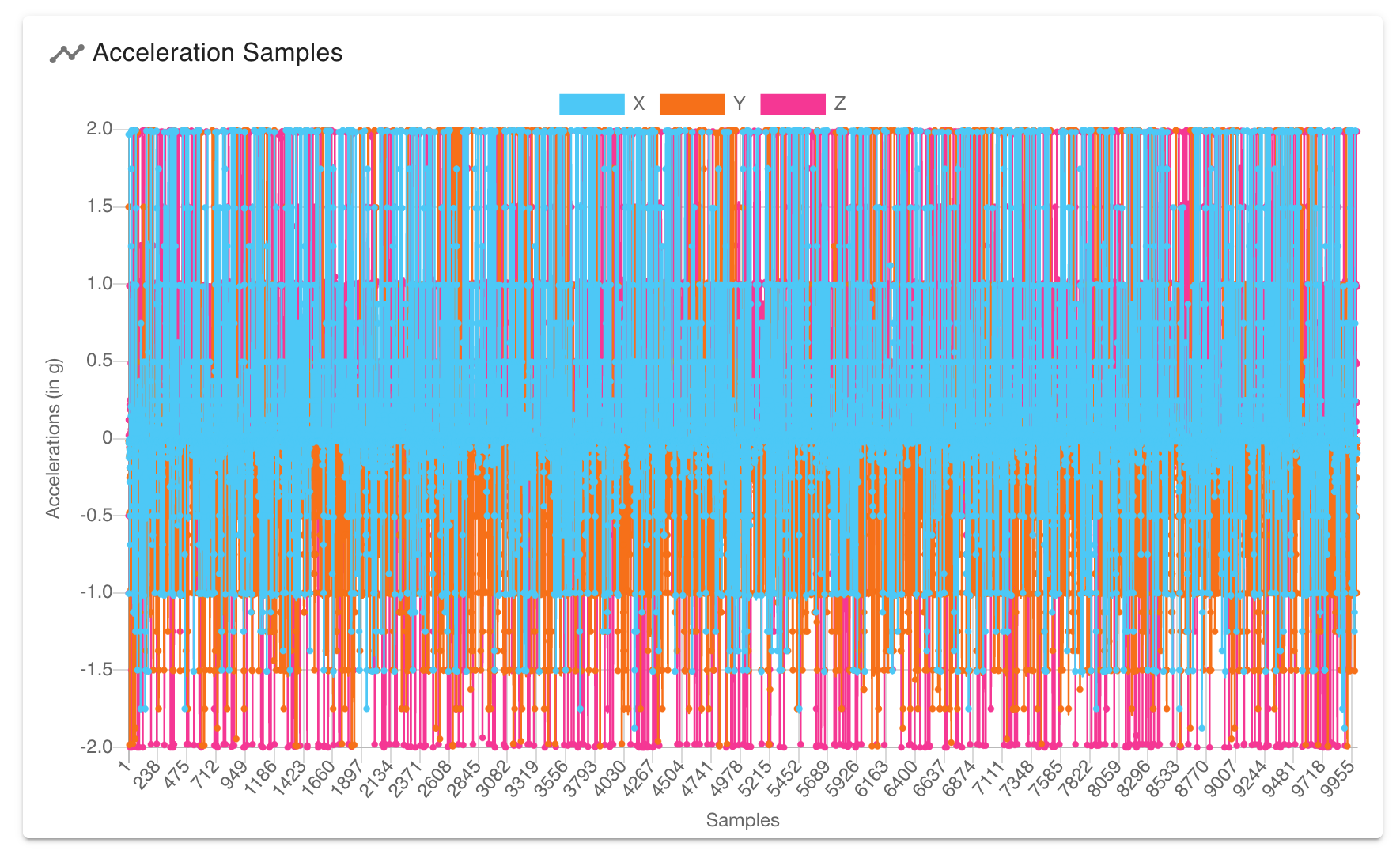
The spurious peaks I see from my LIS3DH accelerometers are very much lower than in your plot, and even lower for my LIS3DSH accelerometer. Perhaps you have either a bad accelerometer, or a wire running right over the chip or right under the PCB.
In the graph I posted, the Y axis scale was between 1.15 and 0.85. Your graph was 1.2 to -0.2. That is a vertical compression of 4.66 times, which visually downplays the peaks.
Even if yours don't have quite as much amplitude, they are still erroneous data on up to 5% of the samples taken. To me, that surely need to be addressed if you want accurate analysis.
-
@ccs86 if you use the Analyse button, I think you will see that the energy in those spurious peaks is much lower than the energy in genuine ringing. Nevertheless, if this proves to be a problem then I will look at randomising the read times somewhat to spread the spectrum out.
-
One could apply a statistical hack if one really knows the problem is every 20 samples, and either the first or last sample in a batch. One can just replace the (known) bad point with the average of the point before and after. This doesn't change the power spectrum significantly. This is equivalent to adding a random Dirac comb of small amplitude (the difference between the correct, missing point and the average) to the data, which has only a very weak effect on the spectrum. The noise floor at frequencies which are harmonics of (sampling rate / 40) will be slightly raised.
-
@dc42
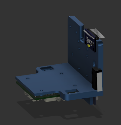
How critical is the way the board is mounted?
Above picture is a mockup with another accelerometer.
As I am only going to use only X axis in this case does it really matter how it is mounted?
-
@mendenmh said in Accelerometer Usage:
One could apply a statistical hack if one really knows the problem is every 20 samples, and either the first or last sample in a batch. One can just replace the (known) bad point with the average of the point before and after. This doesn't change the power spectrum significantly. This is equivalent to adding a random Dirac comb of small amplitude (the difference between the correct, missing point and the average) to the data, which has only a very weak effect on the spectrum. The noise floor at frequencies which are harmonics of (sampling rate / 40) will be slightly raised.
As a straightforward fix I think that is a great idea.
-
I did some more testing and found something interesting. This makes me think that the erroneous spikes don't have anything to do with wiring.
Running back to back tests, with the only change being the inclusion / omission of the "X" parameter in the M956 call (just X axis, or XYZ):
Just X:

XYZ:

Just X still has some spike on the 20 sample intervals, but they appear much worse when logging all 3 axes (~double).
And here are the analyzed results. Not vastly different, but different enough to warrant elimination of that bad data:


-
Somewhat off topic, but this is wild. Here is the analysis of X at 5k / 10k / 15k accel. I did not expect such a big difference when increasing accel to 15k. Makes me suspicious:
5k:

10k:

15k:

-
At this point, I am getting almost no overflows reported, without actually changing anything. Odd.
Is it possible to log at faster than 1344 Hz? The sensor seems to be capable of 5000 Hz, but the "S" parameter doesn't seem to work in the M955 command. I have only ever gotten 1344 Hz and 400 Hz replies in the console.
Also, DWC seems to infer a sampling rate of 1331 Hz, while RRF says 1344 Hz. Only a 1% difference, but I'm guessing it shifts the analysis result slightly. Not sure whether DWC is accurately sensing a 1331 Hz logging rate, on a desired 1344 Hz. Or, if it should be changed to match.
-
@ccs86 said in Accelerometer Usage:
Somewhat off topic, but this is wild. Here is the analysis of X at 5k / 10k / 15k accel. I did not expect such a big difference when increasing accel to 15k. Makes me suspicious:
If the time taken to accelerate or decelerate is about half the period of ringing, that will tend to suppress the ringing. That is how DAA worked. I suggest you calculate the acceleration/deceleration time, i.e. the feed rate of your test move in mm/sec divided by the acceleration.
-
@ccs86 said in Accelerometer Usage:
Is it possible to log at faster than 1344 Hz? The sensor seems to be capable of 5000 Hz, but the "S" parameter doesn't seem to work in the M955 command. I have only ever gotten 1344 Hz and 400 Hz replies in the console.
In theory the code support 5kHz, but it's unlikely to work when using a direct SPI connection. The LIS3DSH supports 1600Hz instead of 1344Hz.
Also, DWC seems to infer a sampling rate of 1331 Hz, while RRF says 1344 Hz. Only a 1% difference, but I'm guessing it shifts the analysis result slightly. Not sure whether DWC is accurately sensing a 1331 Hz logging rate, on a desired 1344 Hz. Or, if it should be changed to match.
The sensor data rate is only approximate (the manufacturer told me +/-20% AFAIR), so RRF measures it and includes the actual data rate in the .csv file.
-
@dc42 said in Accelerometer Usage:
@ccs86 said in Accelerometer Usage:
Somewhat off topic, but this is wild. Here is the analysis of X at 5k / 10k / 15k accel. I did not expect such a big difference when increasing accel to 15k. Makes me suspicious:
If the time taken to accelerate or decelerate is about half the period of ringing, that will tend to suppress the ringing. That is how DAA worked. I suggest you calculate the acceleration/deceleration time, i.e. the feed rate of your test move in mm/sec divided by the acceleration.
Is that calculation only valid with jerk set to zero, or do you think it holds?
-
@dc42 said in Accelerometer Usage:
@ccs86 said in Accelerometer Usage:
Is it possible to log at faster than 1344 Hz? The sensor seems to be capable of 5000 Hz, but the "S" parameter doesn't seem to work in the M955 command. I have only ever gotten 1344 Hz and 400 Hz replies in the console.
In theory the code support 5kHz, but it's unlikely to work when using a direct SPI connection. The LIS3DSH supports 1600Hz instead of 1344Hz.
Also, DWC seems to infer a sampling rate of 1331 Hz, while RRF says 1344 Hz. Only a 1% difference, but I'm guessing it shifts the analysis result slightly. Not sure whether DWC is accurately sensing a 1331 Hz logging rate, on a desired 1344 Hz. Or, if it should be changed to match.
The sensor data rate is only approximate (the manufacturer told me +/-20% AFAIR), so RRF measures it and includes the actual data rate in the .csv file.
Is there a reason that we can't set a specific sampling rate with the "S" parameter, as documented?
and do you have any thoughts on the erroneous spike data I posted above?
-
I discovered in my setup that attaching the accelerometer directly to the coils of a driven stepper motor produces less than useful results.

-
@ccs86 said in Accelerometer Usage:
Is there a reason that we can't set a specific sampling rate with the "S" parameter, as documented?
The accelerometer chip only supports a few specific sampling rates. You can specify the S parameter and the firmware will pick the nearest available one. Send M955 P# where #is the accelerometer ID to find which one has been selected.
-
@94v0 said in Accelerometer Usage:
I discovered in my setup that attaching the accelerometer directly to the coils of a driven stepper motor produces less than useful results.
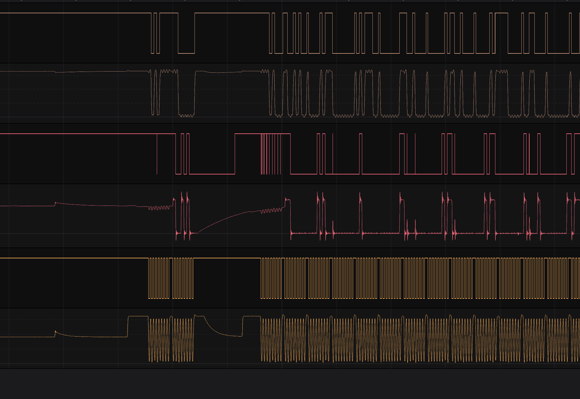
That wasn't the problem, the combination of Mini5+ and LIS3DSH does seem to be pretty sensitive to the quality of the wiring. I thought I'd get away with some shielded DB9 cable, but there's obviously a lot being coupled along the length.
I think the CAT6a I have has individual shielding on the pairs, I'm going to try that and see how it goes. Unfortunately my tool board is a 1.0 so I didn't get this sensor connected to the CAN bus like everything else.

I guess the most optimal solution is to make an absolutely minimal version of the SAMMYC21 development board with the LIS3DSH and CAN transceiver on board, drop the pin headers and the USB UART side of things.
-
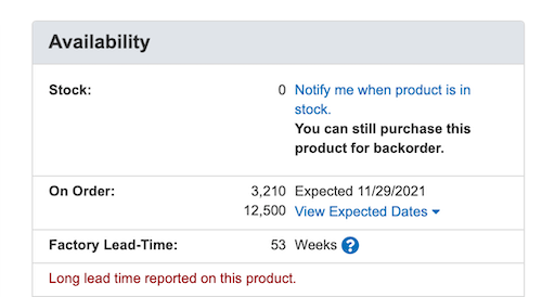
Digikey and Mouser have quite literally no stock of that chip, and only a couple of thousand expected before 2022 across all the variants. Other than scalpers selling them in 2 quantity for $20 each, that's not really an option sadly.

-
@94v0 I updated the accelerometer wiki page recently with details of the cables I used, which are 1m long and work with the Duet 3 Mini. I think the secret is to keep the CS wire away from the other signal wires.
-
@dc42 said in Accelerometer Usage:
@ccs86 said in Accelerometer Usage:
Is there a reason that we can't set a specific sampling rate with the "S" parameter, as documented?
The accelerometer chip only supports a few specific sampling rates. You can specify the S parameter and the firmware will pick the nearest available one. Send M955 P# where #is the accelerometer ID to find which one has been selected.
It looks like the sensor does jump from:
HR / normal (1.344 kHz);
to
Low-power mode (5.376 kHz)
Have you tried that highest rate? I can't get RRF to go above the 1344 Hz
-
@ccs86 I haven't tried the higher sampling rate. My guess is that you won't be able to use that rate except for very short sampling times, without getting overrun errors. The resolution at that speed is only 8-bit, which may not be sufficient. The LIS3DSH does 1600Hz @ 16 bit resolution.
-
@dc42 said in Accelerometer Usage:
@ccs86 I haven't tried the higher sampling rate. My guess is that you won't be able to use that rate except for very short sampling times, without getting overrun errors. The resolution at that speed is only 8-bit, which may not be sufficient. The LIS3DSH does 1600Hz @ 16 bit resolution.
Cool. I actually was able to get some logs at 8-bit 5376 Hz. I'm not sure the loss in resolution is worth the increased sampling rate, with these low magnitude vibrations.
Are we any closer to testing input shaper on Maestro hardware?