Help with NPN probe installation on Duet3 6HC
-
Hi, I've been trying to install this sensor as an endstop (link at the end) on the OI_2 port configured as an input (M574 Y1 S1 P"!io2.in").
Even though I have the correct voltage on the input pin, the Duet 3 6HC always read the input as "no".
Any idea why?
Thanks.
Link to sensor : reference 729-5107 on https://fr.rs-online.com/
-
How exactly do you have it wired?
Is it NPN or PNP?
-
-
I wonder if @fcwilt has any ideas. I know he's tested a lot of these style probes.
-
@anthoval said in Help with NPN probe installation on Duet3 6HC:
Hi, I've been trying to install this sensor as an endstop (link at the end) on the OI_2 port configured as an input (M574 Y1 S1 P"!io2.in").
Even though I have the correct voltage on the input pin, the Duet 3 6HC always read the input as "no".
Any idea why?
Thanks.
Link to sensor : reference 729-5107 on https://fr.rs-online.com/
What are the voltages you are seeing when the probe is activated and not activated?
The specs suggest the logic low voltage is not going to be low enough.
And just out of curiosity how are you going to mount this on your machine?
Thanks.
Frederick
-
@fcwilt Sorry for my late response.
When the probe is activated, the voltage is 24V. When it is not, the voltage is 0V.
The datasheet shows that the sensor generates a current <= 100 mA, which might not be enough for the Duet to read.I have designed a small PCB and used a relay in order to use the sensor as intended.
I don't know yet how I am going to mount it, the best option would be to 3d print something.
-
-
@anthoval said in Help with NPN probe installation on Duet3 6HC:
@fcwilt Sorry for my late response.
When the probe is activated, the voltage is 24V. When it is not, the voltage is 0V.
The datasheet shows that the sensor generates a current <= 100 mA, which might not be enough for the Duet to read.Normally a NPN probe would output a low voltage when activated and a high voltage when not activated.
The voltages are fine and the current is not an issue.
But the way I read the datasheet when the config wire is connected to ground the output is PNP.
Can you clarify?
Frederick
-
@anthoval said in Help with NPN probe installation on Duet3 6HC:
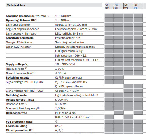
729-5107
The datasheet at https://docs.rs-online.com/2e20/0900766b816e114c.pdf indicates that for the -5107 variant the output is PNP.
-
@fcwilt in my case, the config wire is connected to +24V : When the laser does not see an object the output is 24V, else it is 0V.
-
@anthoval it looks like the model you have is a PNP sensor:
The documentation suggests using a resistive voltage divider to connect a PNP sensor:
https://duet3d.dozuki.com/Wiki/Connecting_a_Z_probe#Section_PNP_output_normally_open_inductive_or_capacitive_sensorFor Duet 3 and 3 Mini: all IOx.in inputs have a 27K pullup resistor to +3.3V, therefore the value of R2 must be low enough to defeat this. We suggest R2 = 2.2K. Then the value of R1 should be 4.7K to 6.8K if the sensor is powered from +12V; or use 10K to 15K if the sensor is powered from +24V.
100mA is far more current than can be sourced/sunk from the IOn.IN pins so that is not the issue.