Large Format Dowell to Duet conversion
-
@dc42 thanks so much for the feedback. Just to clarify: if I use either of the expansion boards I can’t change the Amps on the pellet extruder motor? How do these drivers change the speed of the motor then? My assumption is that to increase or decrease speed the driver is varying a signal that varies both volts and amps? Or does it just vary the speed of the pulses? I’ll order the larger of the two expansion decks as we might add an additional extruder to add a flexible material as a sealant material one day.
Many thanks!
Charles
-
@chrishamm great info! Thank you so much. I will defo run a very powerful fan over the mobo and expansion board. Do you know of a suitable model that will plug into the board please? Many thanks again, Charles
-
@charles-fraser said in Large Format Dowell to Duet conversion:
it just vary the speed of the pulses?
Basically, yes. The current setting would be done on the external driver itself if you chose to continue to use it. The current would basically determine the amount of torque the motor has, but it's also put in balance with heat generated by the motor and the amount of back emf that gets generated at high speeds. It's a complex thing.
For motors that are directly connected to the Duet you can set the current in software. That's the main difference that we're pointing at. For external drivers the Duet has less control over what they do.
-
The best fan for cooling would depend a bit on your electronics enclosure. If you have the space, a 120mm Noctua fan blowing at the edge of the board so it can blow across front and back would be a good option.
-
@charles-fraser said in Large Format Dowell to Duet conversion:
@dc42 thanks so much for the feedback. Just to clarify: if I use either of the expansion boards I can’t change the Amps on the pellet extruder motor?
If you use the EXP3HC expansion board to drive the extruder then you will be able to adjust the current from the software. If you use the EXP1HC and the existing microstepping driver then the current will be controlled by the switches on the driver as it is now.
-
@phaedrux cooli I use noctua on my threadripper, thanks
-
@dc42 thank you! I guess it would be best not to use the external stepper motors then
-
Hi dear @dc42 & @chrishamm @Phaedrux
The Duet 3 mainboard and 3-E-3HC expansion board have now arrived. I have begun labelling the wires of this massive printer and have crimpped together the connectors for the motors: 4X Nema 17 (z axis) and 2X Nema 23 (X and Y axis).

I am going to use the expansion board to drive the nema 17 motor for the pellet extruder. I will also get the daughterboard that can handle the K-type thermocouples as that is what both the extruder and the bed use. Q1: Can the daughter board manage 2X thermocouple please?
I have the extruder on a mosfet that takes the load from the PSU directly to increase efficiency.
I also have the massive mattress sized bed on a relay that when banged (bangbang mode) opens a gate that powers the bed directly from the mains supply. That thing is a beast and we had to build a special power supply from the mains because it would melt all my plug sockets on the wall.
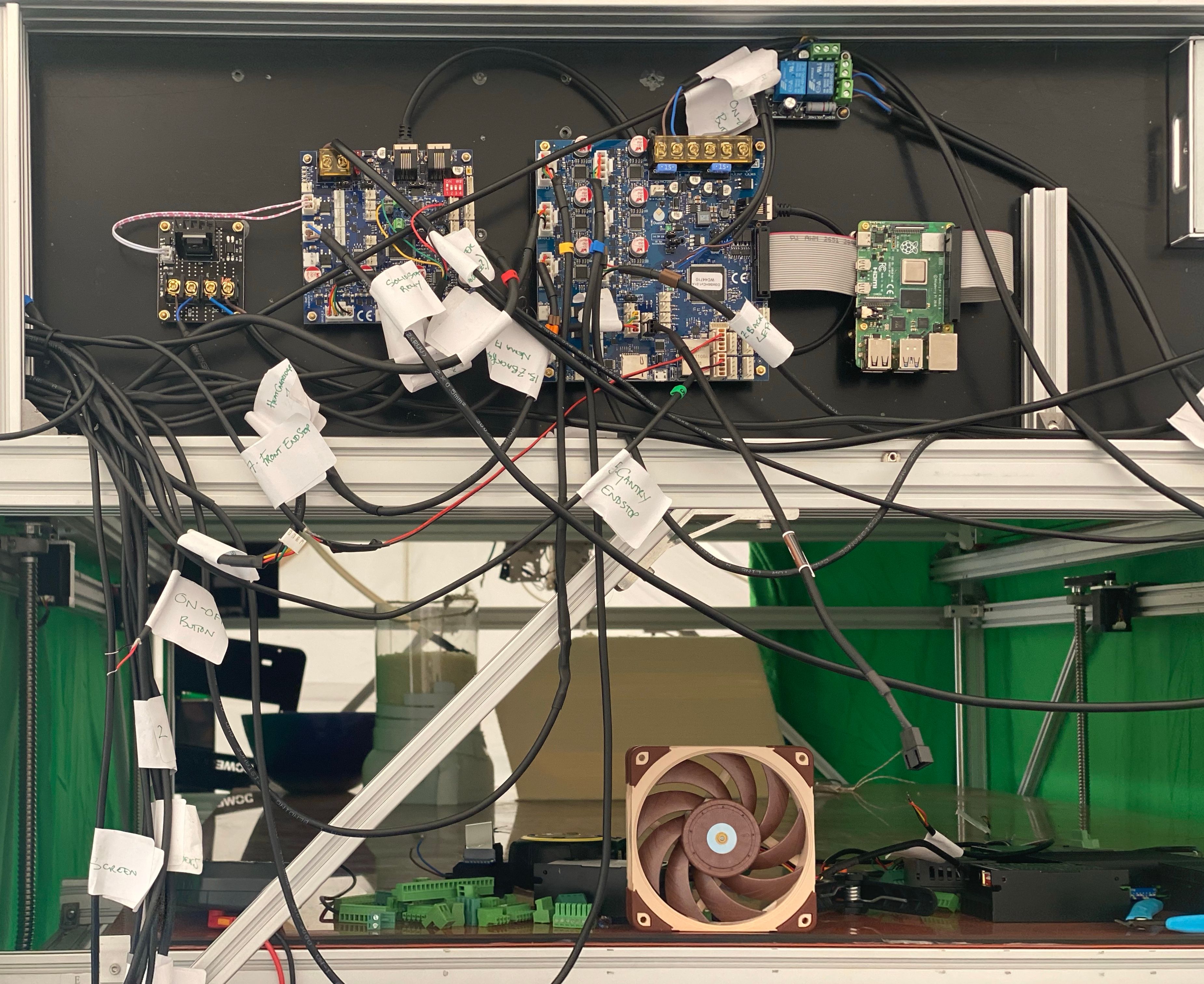
My main question is: what kind of power supply unit do I need to provide enough power for all of this? I am looking for a 1000w supply and can’t seem to work out if my current PSU is fit for the task. Also it goes through this little relay that takes power frolm the mains and routes it to the psu, the bed relay, the on-off switch and two inputs to the board. I provide pics below. Please could you advise me on how to wire all this together and if I should get a new more powerful or different psu. It says 24V on it but no 12V and the Duet 3 says 12V on it. But does the little on off relay transform that somehow. I cant work it out. I have supplied more pics below
Many thanks,
Charles


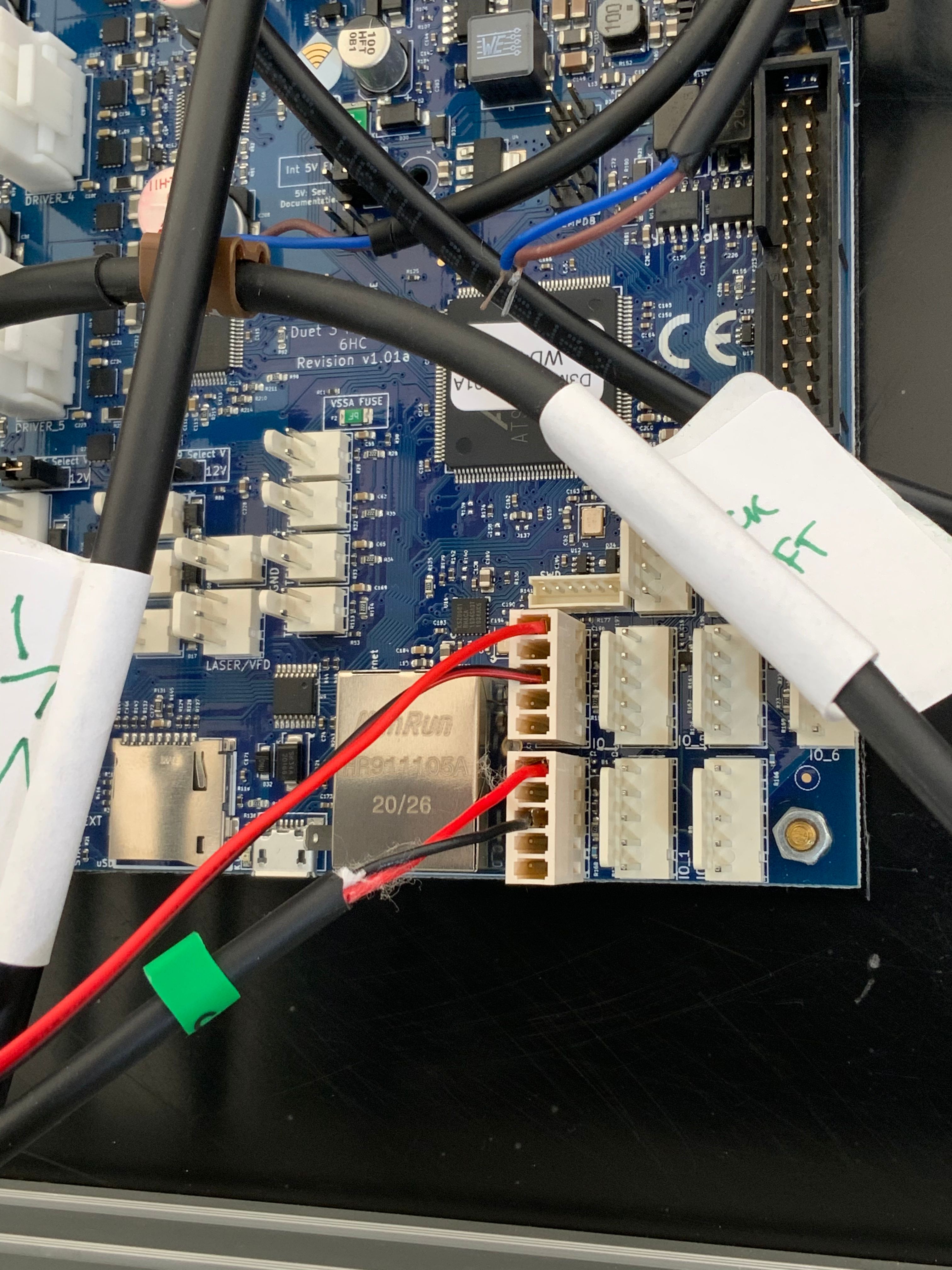
From 12 o'clock clockwise around that is On off switch (yellow, blue, brown), Mains Power (brown blue (the earth is connected to the frame of the printer - is this safe?), then power to the PSU (blue brown), then 5v in brown blue, then signal blue brown. Where should all these go in the board please?


p.s: Once I work it out I will print this new housing with the fans and higher risers for the boards. I have those ordered.


-
@charles-fraser said in Large Format Dowell to Duet conversion:
Q1: Can the daughter board manage 2X thermocouple please?
Yes, each daughter board handles 2 thermocouples. Keep the thermocouple wires away from stepper motor cables, or else shield them.
@charles-fraser said in Large Format Dowell to Duet conversion:
My main question is: what kind of power supply unit do I need to provide enough power for all of this? I am looking for a 1000w supply and can’t seem to work out if my current PSU is fit for the task.
As you are using a mains- voltage bed heater, the PSU need to power only the Duet itself (which needs very little power), the stepper motors, and any low-voltage heaters. Do the pellet extruder heaters work from low voltage, or from mains power via a SSR? I can see one SSR in your photo: does it control the bed heater or the pellet extruder heater(s)?
The Duet 2 is usually run from 24V. The 12V marking you can see on it is probably by the voltage selection jumper for low-current OUT ports, or for the auxiliary 12V output.
I can guess at the reason for one of the two blue relays (to latch power to the PSU), but not the other one. Can you trace a schematic of the relay board?
-
@dc42 Hi there, thanks so much for your reponse.
Both the extruder heater (80w) and heated beds are on an extermal mosfet and relay as indicated in the attached schematic.
I have drawn up the wiring I have managed to put together so far with little green questions marks where I don't know where to put those wires or have some questions. Any advice would be super appreciated. Many thanks, Charles
schematic attached

-
For the bed heater the inputs of the SSR would come from a heater output on the Duet3. Since the SSR uses a low voltage signal input, it doesn't matter so much which heater out put on the Duet3 you use. There is a high power heater output (out_0) in the covered screw down terminals that would normally be used for a high powered heater, but you could use a regular output like Out_1 as well.
The thermocouple board would go onto the Duet3 itself.
https://duet3d.dozuki.com/Wiki/Thermocouple_daughter_board
https://duet3d.dozuki.com/Wiki/Connecting_thermocouplesYou should also reference the wiring diagram, getting started guide for duet3, and the duet3 hardware overview.
https://duet3d.dozuki.com/Wiki/Duet_3_Mainboard_6HC_Wiring_Diagram
https://duet3d.dozuki.com/Wiki/Getting_Started_With_Duet_3#main
https://duet3d.dozuki.com/Wiki/Duet_3_Mainboard_6HC_Hardware_OverviewFor the protective earth connection, it should be going to your PSU as well. Connecting the metalwork of the frame is also a good idea in the off chance that a high voltage connection makes contact with it. Keeping the high voltage wires isolated and protected is also a must.
See what other questions you have left after reviewing those documents.
-
Thank you so much. I will have a look again. If you could please quickly explain where to connect the 5v in and signal connector to that little on off relay that would really help. Thanks again! Charles
-
@charles-fraser The power supply is 350W as stated in the name LRS-Wattage-Voltage. You can also calculate the wattage by multiplying the output voltage (24V) by the amperage (14.6A). It should be more than adequate to drive the Duet 3 MB6HC mainboard and a (number of) expansion board(s).
-
-
@charles-fraser said in Large Format Dowell to Duet conversion:
X & y end stop, is this wiring correct:
I'll try and direct you to existing documentation as much as possible.
")
https://duet3d.dozuki.com/Wiki/Connecting_endstop_switches
Duet 3: connect the switch between the IN and GND pins of your chosen IO_x connector.
Can I assume these are normal microswitches? It looks like you've connected the endstops to 3.3v and GND. The red wire needs to move down one spot to the
IO_#.inpin.@charles-fraser said in Large Format Dowell to Duet conversion:
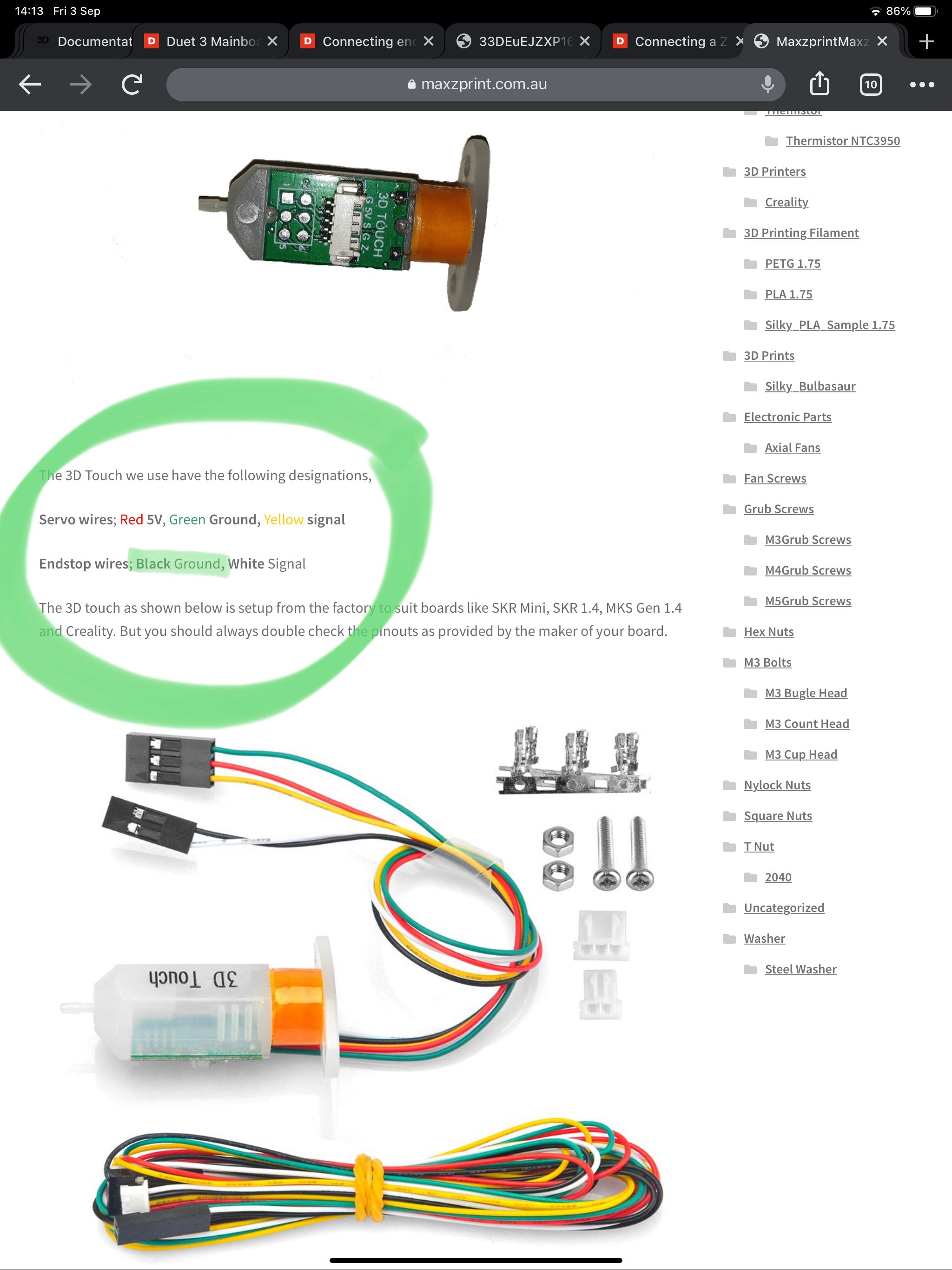
The ‘3D Touch v3.0’ z probe (cheap version of BL touch) has an extra ground I don’t know what to do with.
Some people leave it disconnected, some people daisy chain it to the existing ground at the bltouch, some run an entirely separate wire for it and connect both grounds to the same pin on the board.
-
@phaedrux I thank you

I will check / change all that. Yes they are just simple end stops. Only two wires coming from them.
The thing I really cant work out is how to wire the on-off switch relay board as per the question marks that come off the wires coming out to the left of that relay board in my “schematic” above. It needs a 5V in and a signal input from the duet. Please advise!
Sorry about all the questions just the best I have made before is some resonant LED circuits and a PC.
Many thanks
Charles -
@charles-fraser said in Large Format Dowell to Duet conversion:
It needs a 5V in and a signal input from the duet.
I'm not super savvy when it comes to relays etc but I think what you want is an external 5v supply for the relay to power it, and then the signal would be coming from the duet using the PS_on function M80/M81 see here: https://duet3d.dozuki.com/Wiki/Power_Wiring
Where does the current printer get the 5v for the relay from?
@charles-fraser said in Large Format Dowell to Duet conversion:
Sorry about all the questions just the best I have made before is some resonant LED circuits and a PC.
Nothing like diving into the deep end.
-
undefinedHi dear @Phaedrux and @dc42
Thanks so much for your help! I've covered your last point re the power relay in item 1. I then have a couple more questions before I power this thing up and try and get some configurations tested if you could help with those too please:
- Regarding the signal cables and 5v cables to the power relay. To answer your question: The 5v and signal cables were connected to the old motherboard. In the article you linked me to it says:
'If you are using an external relay to control mains power to the PSU, you can wire either the +5v or +3.3v (depending on what your relay requires) outputs from the duet in to the positive terminal of the relay, and wire the ground terminal of the relay to the PS_ON output on the duet. If you are using a mechanical relay and it does not include a flyback diode of some sort, you will need to wire one in parallel with the relay signal.'
Please note the 5v pin next to the PS_ON is an input and as it is has a diode in series with it will not output 5v. If you need 5v to power a relay of some sort you need to use the expansion connector pin 1 or the 5v pin on the vfan jumper.'
I can't seem to find 'vfan' jumper on the Duet 3. Please advise?
- I have connected the other wires to the ports listed in this diagram:
- undefined Green Machine Wiring Table
Do you think the Noctua good in the PWM lazer three pin connector?
Do you think the thermocouple is okay with the cable running alongside the extrudor motor cable to the gantry? Both bed and nozzle thermocouples are in the daughterboard of the expansionboard.
- Is there any-way to make a firmware config using the online configurator that has more than one z axis or do I need to edit the code in Visual Code Studio after I make a config file just adding those extra motors to the list?
4a Is there any way to use the Duet Web Control (DWC) to monitor the print live over webcam?
4b Using Cura as a slicer, is it possible to delete a part during printing to move onto the next one as with Octoprint or is it best for me to use Octoprint for the webcam monitoring and part deleting? If so I will either flash the configs straight to the mobo and run octoprint to print through the usb or set the raspberry Pi up with dual boot: The Duet Rasperian image for setting up configs and then the Octoprint image for printing that way.
- The only other thing is working out how to connect the screen at the front but it's not a duet screen so I am not going to worry about this till after I have the printer working again.
Many many thanks
Charles

-
Hi gents, so sorry so many questions but here are some more re firmware config:
- Heaters:
Sensors:
I have the daughterboard plugged into the expansion board for the k-type thermocouple for my bed and nozzle. Which of the options should I choose? I can’t tell from the list.
- Z probe config
I have my 3D touch plugged into the IO2 port of the expansion board but the config options for the ‘z probe’ and BL touch
It wants: PWM Control Channel’ for BL touch. Should I use this as the only assigned option for the 3D Touch?
-
@charles-fraser in the IO Mapping page:
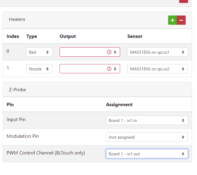
EDIT: I see that the daughter board is plugged into the EXP3HC. the config tool doesn't support that directly, so you will need to edit the config.g file. In the M308 commands, change spi.cs1 to 1:spi.cs0 and change spi.cs2 to 1:spi.cs1.