Duet3D Logo Duet3D
    • Tags
    • Documentation
    • Order
    • Register
    • Login

    Large Format Dowell to Duet conversion

    Scheduled Pinned Locked Moved
    Duet Hardware and wiring
    14
    362
    34.6k
    Loading More Posts
    • Oldest to Newest
    • Newest to Oldest
    • Most Votes
    Reply
    • Reply as topic
    Log in to reply
    This topic has been deleted. Only users with topic management privileges can see it.
    • Charles Fraserundefined
      Charles Fraser @T3P3Tony
      last edited by

      @t3p3tony said in Large Format Dowell to Duet conversion:

      M98 P"0:/sys/config.g"

      	M98 P"0:/sys/config.g"
      Error: M308: Unknown sensor type name "thermocouplemax3185"
      Error: M307: Heater 0 not found
      Error: M143: Heater 0 does not exist
      
      T3P3Tonyundefined 1 Reply Last reply Reply Quote 0
      • Charles Fraserundefined
        Charles Fraser @T3P3Tony
        last edited by

        @t3p3tony Working on a diagram to illustrate the tests I am doing

        T3P3Tonyundefined 1 Reply Last reply Reply Quote 0
        • T3P3Tonyundefined
          T3P3Tony administrators @Charles Fraser
          last edited by

          @charles-fraser this is weird: "thermocouplemax3185" as you have

          M308 S0 P"1.spi.cs0" Y"thermocouple-max31856"

          I will see if I can reproduce this issue

          www.duet3d.com

          1 Reply Last reply Reply Quote 0
          • T3P3Tonyundefined
            T3P3Tony administrators @Charles Fraser
            last edited by

            @charles-fraser I can recreate this issue with the thermocouple on expansion boards not being set right so we will look inot that this end. In the mean time we can work on the rest of the config.

            www.duet3d.com

            Charles Fraserundefined 1 Reply Last reply Reply Quote 0
            • Charles Fraserundefined
              Charles Fraser @T3P3Tony
              last edited by Charles Fraser

              @t3p3tony

              Hi Tony, welcome to “the other end of the machine”

              894F6533-E5EB-45EE-81B4-5DD0932184ED.jpeg

              BA76EB62-870A-47D6-8B7A-AAE898D1F9DF.jpeg

              B0B03B97-9399-483C-84A7-198BF3905C2A.jpeg

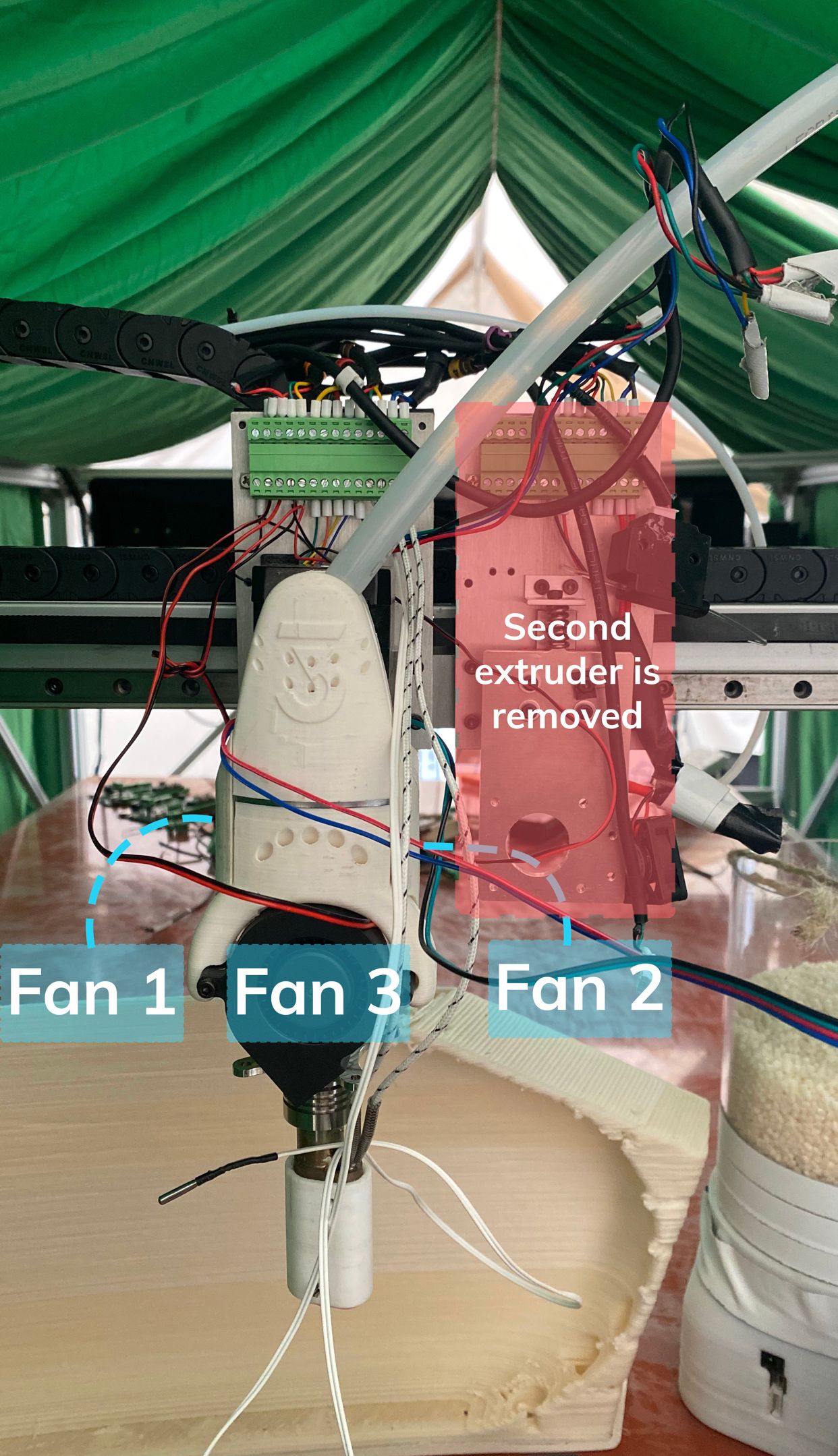
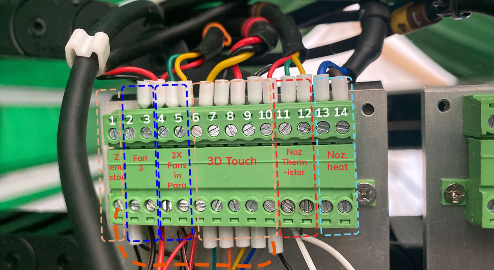
              I test for continuity with Ohms on my RadioShack Multimeter and get 140 accross two wires on thermistor disconnected and connected To points 11-12. The same reading when board is on or off. I had some readings accross the noz thermistor and noz heat cartridge terminals (testing accross points 11 and 13) when the heating cartridge was disconnected but when I connected the heat cartridge it stopped. Nothing at all. I think there is a damaged wire somewhere. I am testing and will let you know results.

              Not sure what you mean about the thermocouple but I keep going as you instruct. My thanks

              T3P3Tonyundefined 2 Replies Last reply Reply Quote 0
              • T3P3Tonyundefined
                T3P3Tony administrators @Charles Fraser
                last edited by

                @charles-fraser ok for the thermocouple there is an issue with the name when used on an expansion board. For now please change the line in config.g to

                M308 S0 P"1.spi.cs0" Y"thermocouplemax31856"
                

                Note I have removed the "-"

                then run

                M98 P"0:/sys/config.g"

                and hopefully we will be back to no errors.

                (and maybe even a reading for bed temperature)

                I hope you find the source of the wiring issue. As a point of reference I would expect the thermistor to have a reading in the vicinity of 10K or 100K at room temperature (they come in many different types so it might be different).

                www.duet3d.com

                Charles Fraserundefined 4 Replies Last reply Reply Quote 0
                • Charles Fraserundefined
                  Charles Fraser @T3P3Tony
                  last edited by Charles Fraser

                  @t3p3tony

                  Thanks Tony I will try that just now. I have just had a long chat with Juan the inventor of opensource Lily Pellet Extruder Website that I have hooked up here printing pellets from a 3mm nozzle and about 500-1000g / hour and costing only 500-1000$ for the extruder. Juan's manufacture partner in Spain has just said he can't fulfill the orders c. 20 orders Juan has for extruders because he is too busy with other stuff so Juan is stuffed and looking for a new manufacture partners. He has some amazing designs for a V2 extruder and a colour system that mixes RMCYB in a liquid master batch into the heated chamber to create colour prints or feed additives like fire resistant chemicals into the liquid masterbatch. Pellets reduce cost of printing 10 x and using a shredder you can shred old prints and certain household waste to create materials for the extruder. It's the whole idea behind the system. We will be at the Additt conference in Bilbao and wonder if you will be there and if you know anyone who might want to process the c. $20k worth of orders for the extruder that can be simply 3D printed for the high temp plastic parts and CNC milled for the auger and hopper? Orders that are on the table now. Perhaps this is something the opensource community here might want to discuss, but he's looking for partners to take the product forwards so I'm going to try and help him find what he needs thereby.

                  Recycle 3D print.jpg

                  I'll send the results from the updated config just now. Thanks
                  Charles

                  1 Reply Last reply Reply Quote 0
                  • Charles Fraserundefined
                    Charles Fraser @T3P3Tony
                    last edited by

                    @t3p3tony

                    Oh no now the Pi won’t start up! It just goes black after the loading text scrolls past after startup!

                    1 Reply Last reply Reply Quote 0
                    • Charles Fraserundefined
                      Charles Fraser @T3P3Tony
                      last edited by

                      @t3p3tony reflashed the SD and it is working again

                      Charles Fraserundefined 1 Reply Last reply Reply Quote 0
                      • Charles Fraserundefined
                        Charles Fraser @Charles Fraser
                        last edited by

                        @charles-fraser

                        Okay so I reflashed the SD and reconnected the pi, the screen worked now. I uploaded the old config and changed the config.g for a copy and paste of the last config.g I posted in here. Now it says:

                        M98 P"0:/sys/config.g"
                        Error: M307: Heater 0 not found
                        Error: M143: Heater 0 does not exist
                        

                        It also turns the fan on and off every second or so - it used to just wirr away very slowly but noisily. now it all seems abit crap.

                         Configuration file for Duet 3 (firmware version 3.3)
                        ; executed by the firmware on start-up
                        ;
                        ; generated by RepRapFirmware Configuration Tool v3.3.3 on Fri Oct 01 2021 16:59:54 GMT+0100 (British Summer Time)
                         
                        ; General preferences
                        G90                                                             ; send absolute coordinates...
                        M83                                                             ; ...but relative extruder moves
                         
                        ; Wait a moment for the CAN expansion boards to start
                        G4 S2
                         
                         
                        ; Drives
                        M569 P0.0 S1                                                    ; physical drive 0.0 goes forwards
                        M569 P0.1 S1                                                    ; physical drive 0.1 goes forwards
                        M569 P0.2 S1                                                    ; physical drive 0.2 goes forwards
                        M569 P0.3 S1                                                    ; physical drive 0.3 goes forwards
                        M569 P0.4 S1                                                    ; physical drive 0.4 goes forwards
                        M569 P0.5 S1                                                    ; physical drive 0.5 goes forwards
                        M569 P1.0 S1                                                    ; physical drive 1.0 goes forwards
                        M584 X0.0 Y0.1 Z0.2:0.4:0.5:0.3 E1.0
                        M350 X16 Y16 Z16 E16  I1                                ; configure microstepping with interpolation
                        M92 X80.00 Y80.00 Z400.00 E420.00          ; set steps per mm
                        M566 X900.00 Y900.00 Z60.00 E120.00        ; set maximum instantaneous speed changes (mm/min)
                        M203 X6000.00 Y6000.00 Z180.00 E1200.00 ; set maximum speeds (mm/min)
                        M201 X500.00 Y500.00 Z20.00 E250.00        ; set accelerations (mm/s^2)
                        M906 X2800 Y2800 Z1200 E1200 I30                      ; set motor currents (mA) and motor idle factor in per cent
                        M84 S30                                                         ; Set idle timeout
                         
                        ; Axis Limits
                        M208 X0 Y0 Z0 S1                                                ; set axis minima
                        M208 X1200 Y2000 Z1600 S0                                       ; set axis maxima
                         
                        ; Endstops
                        M574 X1 S1 P"io0.in"                                            ; configure active-high endstop for low end on X via pin io0.in
                        M574 Y1 S1 P"io1.in"                                            ; configure active-high endstop for low end on Y via pin io1.in
                        M574 Z1 S2                                                      ; configure Z-probe endstop for low end on Z
                         
                        ; Z-Probe
                        M558 P9 C"^1.io1.in" H100 F120 T6000                            ; set Z probe type to switch and the dive height + speeds
                        G31 P500 X0 Y0 Z2.5                                             ; set Z probe trigger value, offset and trigger height
                        M556 S50 X0 Y0 Z0                                               ; set orthogonal axis compensation parameters
                        M557 X15:215 Y15:195 S20                                        ; define mesh grid
                         
                        ; Heaters
                        M308 S0 P"1.spi.cs0" Y"thermocouplemax31856"
                        M307 H0 B1 S1.00                                                ; enable bang-bang mode for the bed heater and set PWM limit
                        M140 H0                                                         ; map heated bed to heater 0
                        M143 H0 S80                                                    ; set temperature limit for heater 0 to 80C
                        M308 S1 P"1.temp0" Y"thermistor" T100000 B3800                 ; configure sensor 1 as thermistor on pin temp0
                        M950 H1 C"1.out1" T1                                              ; create nozzle heater output on out1 and map it to sensor 1
                        M307 H1 B0 S1.00                                                ; disable bang-bang mode for heater  and set PWM limit
                        M143 H1 S300                                                    ; set temperature limit for heater 1 to 300C
                         
                        ; Fans
                        M950 F0 C"out8" Q500                                            ; create fan 0 on pin out8 and set its frequency
                        M106 P0 S0 H T45                                                ; set fan 0 value. Thermostatic control is turned on
                        M950 F1 C"out9" Q500                                            ; create fan 1 on pin out9 and set its frequency
                        M106 P1 S1 H-1                                                  ; set fan 1 value. Thermostatic control is turned off
                         
                        ; Tools
                        M563 P0 S"lily" D0 H1 F0:1                                      ; define tool 0
                        G10 P0 X100 Y100 Z0                                             ; set tool 0 axis offsets
                        G10 P0 R0 S0                                                    ; set initial tool 0 active and standby temperatures to 0C
                         
                        ; Custom settings are not defined
                        
                        1 Reply Last reply Reply Quote 0
                        • Charles Fraserundefined
                          Charles Fraser @T3P3Tony
                          last edited by

                          @t3p3tony not sure if you saw the latest above?

                          1 Reply Last reply Reply Quote 0
                          • T3P3Tonyundefined
                            T3P3Tony administrators @Charles Fraser
                            last edited by

                            @charles-fraser said in Large Format Dowell to Duet conversion:

                            I am testing and will let you know results.

                            waiting to hear back about how the wiring tests went.

                            www.duet3d.com

                            Charles Fraserundefined 2 Replies Last reply Reply Quote 0
                            • Charles Fraserundefined
                              Charles Fraser @T3P3Tony
                              last edited by Charles Fraser

                              @t3p3tony

                              Hi Tony, I have made a table of the tests using the Ohms meter on the Radioshack Multimeter which gives continuity across all the different positions 1-14 shown in the image in my earlier post 'welcome to the front of the machine':

                              A new sheet on the 'Wiring Table' doc named 'continuity' explains which positions give continuity when connected and what reading thereupon

                              07783D58-4311-4AD5-939E-717D5F2583EA.jpeg

                              1 Reply Last reply Reply Quote 0
                              • Charles Fraserundefined
                                Charles Fraser @T3P3Tony
                                last edited by

                                @t3p3tony I hope this finds you well? I'm away for a while I just would like your help understanding what these results mean? basically everything connected to the board is connecting to everything else. How is this possible? How could we determine if the board is fried so this is all connecting everyting or if there is some wire rubbed down but I just dont understand how it is connecting everything? Charles

                                T3P3Tonyundefined 1 Reply Last reply Reply Quote 0
                                • T3P3Tonyundefined
                                  T3P3Tony administrators @Charles Fraser
                                  last edited by

                                  @charles-fraser I am trying to recreate a another issue, when done I will run through the table you have created and report back here.

                                  I did have a quick look right now and the first thing i wanted to see was the thermistor:

                                  Thermistor +or- 12 11 Continuity 120 m ohm

                                  120 mili Ohm is not in the right ballpark but this may be because you are measuring from the terminal block with one side still connected to the Duet.

                                  before you go away can you do a simpler test: unplug the 2 pin connector from temp 1 on the expansion board and test the resistance of the thermistor from that connector.

                                  i.e.
                                  e2d2dc78-2835-4bd2-a0b5-65d723c5a217-image.png

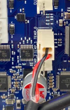
                                  you are testing between the back and red wires in the above image.

                                  www.duet3d.com

                                  Charles Fraserundefined 3 Replies Last reply Reply Quote 0
                                  • Charles Fraserundefined
                                    Charles Fraser @T3P3Tony
                                    last edited by

                                    @t3p3tony Thank you Tony, I will do that when back on Wednesday eve. Very best, Charles

                                    1 Reply Last reply Reply Quote 0
                                    • Charles Fraserundefined
                                      Charles Fraser @T3P3Tony
                                      last edited by

                                      @t3p3tony

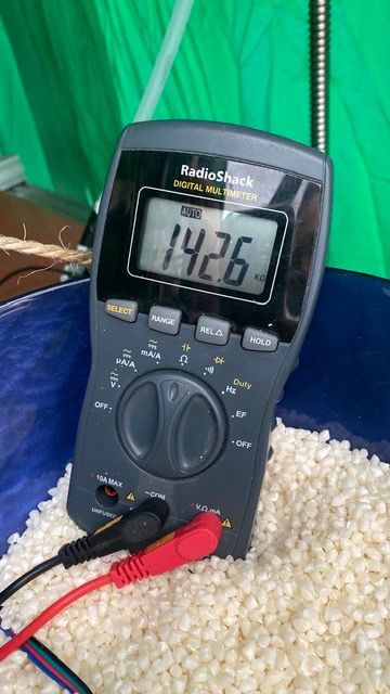
                                      Hi Tony, this is what I get across the thermistor measured at the board (but disconnected)

                                      581F2A5A-4FFB-4EEC-8405-DB409633AE1E.jpeg !

                                      Are we sure it’s not Mega Ohms?

                                      1 Reply Last reply Reply Quote 0
                                      • Charles Fraserundefined
                                        Charles Fraser @T3P3Tony
                                        last edited by

                                        @t3p3tony any idea when you might be able to look at this all please Tony? Thanks

                                        T3P3Tonyundefined 1 Reply Last reply Reply Quote 0
                                        • T3P3Tonyundefined
                                          T3P3Tony administrators @Charles Fraser
                                          last edited by

                                          @charles-fraser ok so that is not right. A thermistor is likely to be between 10K and 200K, there are a few which may be a bit more but that looks almost open circuit - 7.97 Meg Ohm. either there are wires misconnected in the wiring block you showed in a previous picture or there is a break in a cable or in the thermistor itself.

                                          Another question with the latest firmware is the bed heater now showing up correctly?

                                          www.duet3d.com

                                          Charles Fraserundefined 1 Reply Last reply Reply Quote 0
                                          • Charles Fraserundefined
                                            Charles Fraser @T3P3Tony
                                            last edited by

                                            @t3p3tony

                                            Hi Tony, i rewired the thermistor and extruder heater. Testing across the thermistor along I get c. 176k. Testing when it’s reconnected at the points that go into the board (as show in your pic above) I get 156k. Perhaps there was a loose wire. Hopefully this fixes it.

                                            54856AAC-A53E-464A-BA8B-AD2EA2079272.jpeg
                                            AD7BDF5C-BFBF-4083-A2DE-5BA44876DE18.jpeg D386D546-F87B-423E-A6AF-190B581A7DF9.jpeg

                                            Regarding the bed. Please refer to the error codes in my last post about this. The thermocouple is not being recognised. We changed the name of the thermistor if you recall as you also had troubles getting the expansion board to recognise the daughterboard / thermistor naming conventions. Should I move the daughterboard / thermocouple and heater for the bed to the mainboard? Could you you please help me with the right commands for the gcode with that? Thanks

                                            T3P3Tonyundefined 1 Reply Last reply Reply Quote 0
                                            • First post
                                              Last post
                                            Unless otherwise noted, all forum content is licensed under CC-BY-SA