Duet Integration with an "AskPower A131" VFD
-
In case they're useful for people, here are notes regarding integration of a Duet 2 with a low cost 1.5KW air cooled spindle from Ebay, controlled by an “AskPower A131” variable frequency drive (VFD) inverter.
Warning
Wiring up a VFD involves high, potentially lethal, voltages and shouldn't be undertaken without appropriate knowledge and experience.1 VFD Mains Wiring
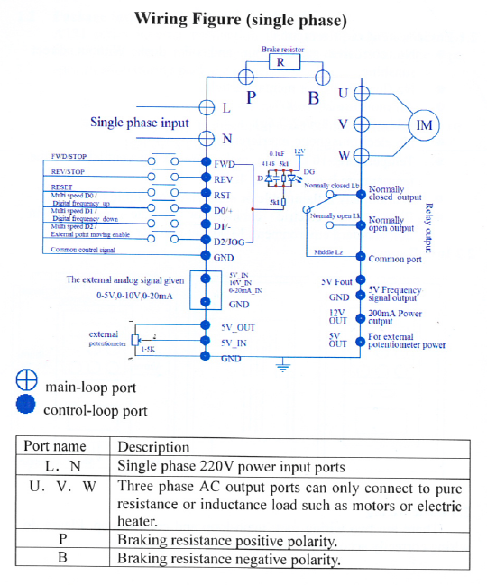
The VFD was connected to 240V mains power via a switch and fuse (13A) using the L and N terminals in accordance with this diagram:
2 Duet to VFD Interface
To enable the speed and direction of the spindle to be controlled by the Duet, a simple interface was built on matrix-board using parts to hand. The schematic is as follows:
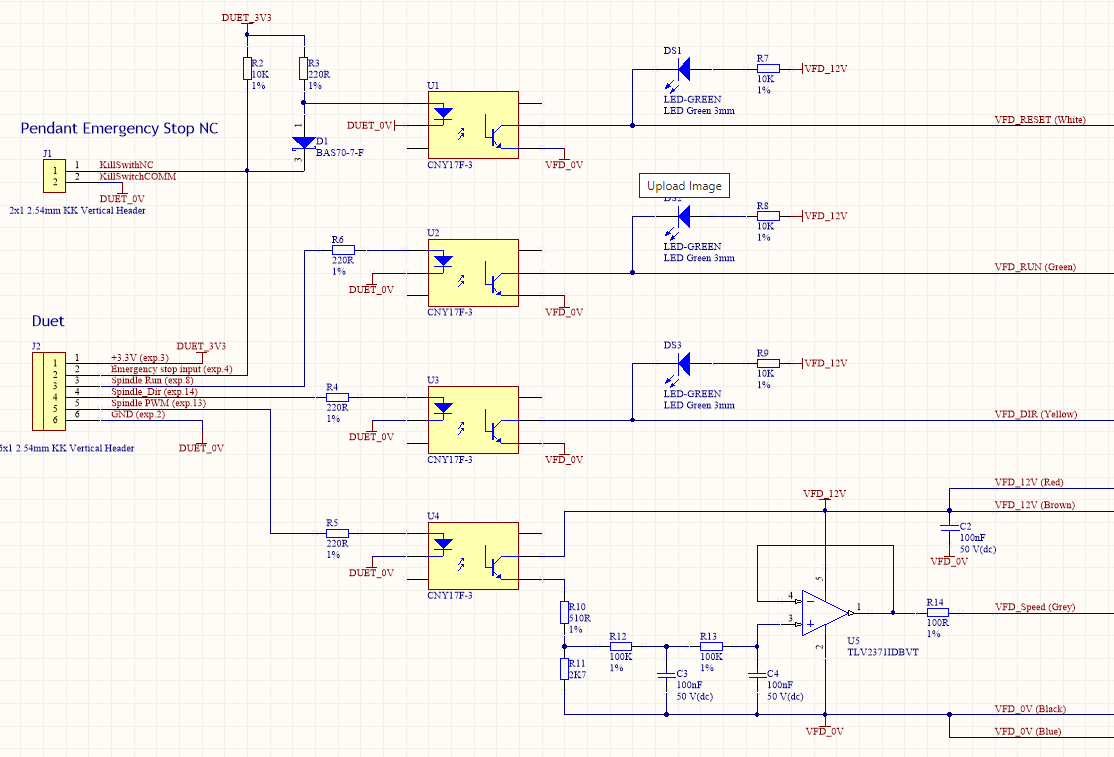
Opto-isolators U1 to U4 electrically isolated the VFD controller from the Duet to avoid ground loops and reduce the risk of damage to the Duet board in the event of a fault/breakdown in the VFD. In addition, they provide the necessary level shifting from the 3.3V logic levels provided by the Duet.Emergency Stop is provided by a normally closed button on the control pendant. In normal operation, this switch holds the Duet Emergency Stop Input low and LED in U1 is held off via D1.
When the Emergency Stop button is pressed, the switch contacts open, applying current to the LED in U1 via R3. This asserts the VFD_RESET line to rapidly stop the spindle. In addition, D1 allows R2 to pull an Emergency_Stop input to the Duet high, so it can pull the spindle up in the Z axis and halt the CNC X-Y stepper motors.The Spindle_Run and Spindle_Dir signals control the spindle ON/OFF state and direction of rotation and drive the VFD's VFD_RUN and VFD_DIR inputs via U2 and U3 respectively.
Light emitting diodes DS1 through DS3 indicate the status of the VFD_RESET, VFD_RUN and VFD_DIR inputs and provided useful for test purposes.
The Spindle_PWM signal from the Duet is passed through U4. R10 and R11 act to limit the PWM signal generated by U4 to an amplitude of 10V, as required by the VFD. The PWM signal is passed through a second order low pass filter formed by R12, R13, C3 and C4 and a unity gain buffer (U5) to drive the VFD_Speed input. A linearity error of around 4% at 5.0V output was measured. This gives a spindle speed of around 12,480 rpm for a 12,000 rpm setting, which was felt to be OK for now. Ideally, the VFD’s frequency output signal would be used to reduce this error.
It may be noted that this circuit is generic and could be used with other VFD such as the HuanYang units.
Duet 2 Connections
The interface board was connected to the Duet 2 expansion connector using the following pins: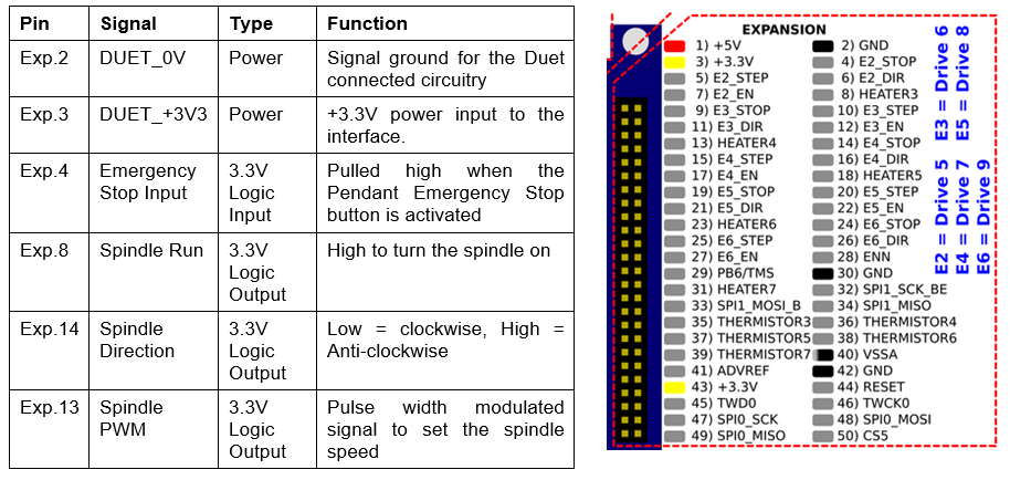
VFD Connections
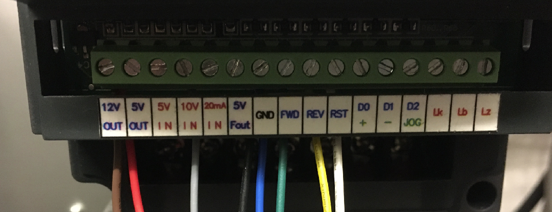
The interface board was wired to the VFD as shown in the photo below. Note that the brown and red wires are both wired to the 12V OUT terminal and the blue and black wires are both wired to the GND terminal.
VFD Configuration
To enable external control, the VFD must be configured using its control panel.
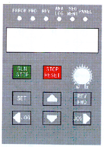
The basic method is as follows:
a) Ensure the VFD is powered and the Spindle is stopped.
b) Press SET to put the VFD into the “Parameter Set” mode.
c) Press the up/down buttons to choose the parameter to be adjusted.
d) Press the SET button again to select the chosen parameter.
e) Press the up/down and left/right buttons to adjust the parameter value to the desired setting. The left/right buttons are used to select which digit of the numeric value is to be changed and the up/down buttons enable the value of the digit to be incremented or decremented. Holding down Up or Down will cause the selected digit to scroll through the values 0 to 9.
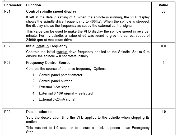
f) Once the value has been set correctly, press SET to store the new value. Alternatively, press STOP to cancel the operation.Using this approach the following parameter values were configured, with all others left at their default values:
Duet Firmware Configuration
The following settings were used for the Firmware Version 3.2 Beta to take advantage of the new CNC spindle control options. However, the settings used for previous versions are included for reference, but commented out.; Tools M563 S"Spindle" P0 D0 H ; Define Tool 0 (our Spindle) G10 P0 X0 Y0 Z0 ; Set tool 0 axis offsets G10 P0 R0 S0 ; Set initial tool 0 active and standby temperatures to 0C ; CNC Emergency Stop M950 J0 C"exp.e2stop" ; Define exp.e2stop as P0 to use as an emergency stop input M581 P0 T0 S1 R0 ; emergency stop (T0) when P0 (E0 end stop) edge occurs ; CNC Mode (Updated for Firmware 3.2) M453 C"exp.13+exp.8+exp.14" Q1000 R24000 T0 ; CNC Mode, PWM frequency 1KHz, max rpm = 24K ; spindle speed PWM pin : exp.13 ; spindle run pin : exp.8 ; spindle direction pin : exp.14 ; CNC Mode (Pre Firmware 3.2) ; M950 P1 C"exp.8" ; use pin 8 on the expansion connector as the VFD enable pin ; M42 P1 S1.0 ; to turn the spindle on ; M42 P1 S0.0 ; to turn the spindle off ; M453 C"exp.13" F1000 R24000 ; spindle speed PWM control using exp.13 pin, ; PWM frequency 1KHz, max rpm = 24KUpdate for Firmware version 3.3RC1
; Configure Tool 0 as the CNC Spindle (Firmware 3.3RC1)
M950 R0 C"exp.13+exp.8+exp.14" Q2000 L500:26200   ; Create spindle index 0, PWM frequency 2KHz,
                                                  ; Lmin:max rpm = tweaked to match actual to target spindle RPM on
                                                  ; and the following connections:
                                                  ; spindle speed PWM pin	: exp.13
                                                  ; spindle run pin 		: exp.8
                                                  ; spindle direction pin 	: exp.14
M563 P0 R0 S"Spindle"                             ; Create Tool 0 with Spindle 0 and call it Spindle
G10  P0 X0 Y0 Z0                                  ; Set Tool 0 axis offsets
M568 P0 F0					  ; Set Tool 0 to default RPM of 0
T0						  ; Select Tool 0 (or make sure generated by CAM)

; CNC Emergency Stop
M950 J0 C"exp.4"                   ; Define exp.4 as P0 to use as an emergency stop input
M581 P0 T0 S1 R0                   ; emergency stop  (T0) when P0 (E0 end stop) edge occurs

; CNC Mode (Firmware 3.3RC1)
M453
Hope this helps someone!
-
@cjm That definitely helps a lot, thanks.
May I presume M3/M4/M5 will then work (being able to set the spindle speed with S<speed> modifier too)?
-
@misan Yes, using the S parameter with M3,M4 sets the spindle speed. M5 just stops the spindle so doesn’t use the speed parameter.
Glad to hear the notes have been of help.
-
@cjm
Update to add VFD spindle feedbackThe AskPower provides a signal, labelled “Fout 5V”, that can be filtered to generate a voltage that is proportional to spindle speed. One way of getting this data into a Duet is to use an Arduino (e.g. mini pro) to convert this signal (called VFD_FREQ in this schematic) into a frequency that can be fed back to the Duet via an opto-isolator as illustrated below.
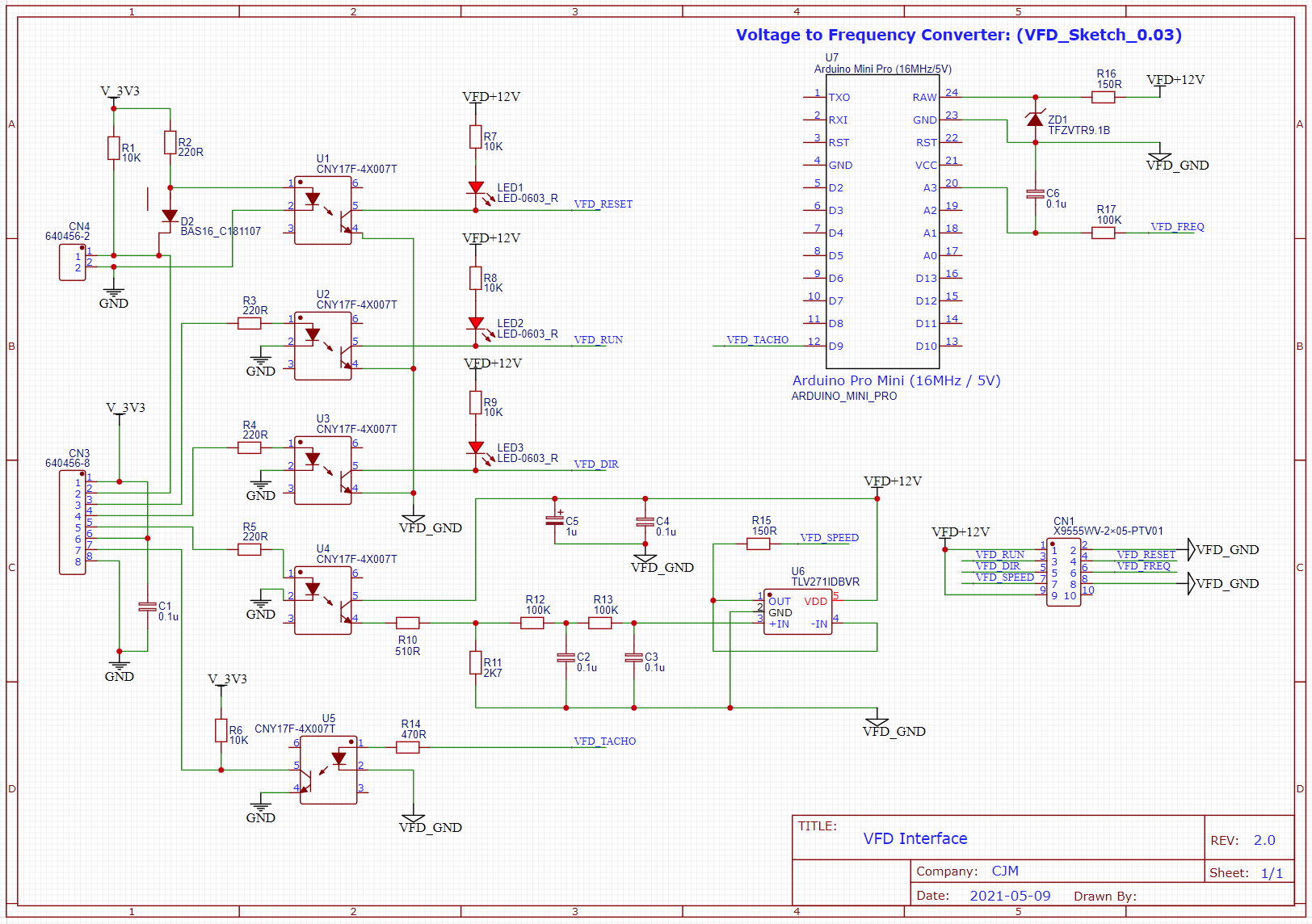
By connecting the opto-isolated square wave to pin exp.pb6 and configuring Fan 0 as below, the spindle rpm can be read as fan rpm using the Duet.
; Fans
M950 F0 C"!fan0+^exp.pb6" Q1000 					; Fan 0 uses the Fan0 output. inverted for PWM, and PB6 as a tacho input with pullup resistor enabled
An arduino script to do the voltage to frequency conversion is:
//  VFD_Sketch_0.03
//
//  License: GPL-3.0
//
//  Helpful reference: https://playground.arduino.cc/Code/FastPWM/
//
//  Sketch to measure a 0 to 5.0V VFD frequency output and generate a
//  tacho pulse whose frequency is proportional to the spindle RPM.
//
//  The VFD frequency output range is 0 -> 5.0V.
//  Using the 16MHz/5V version of the Mini Pro this will
//  deliver an ADC range of 1024 LSB (i.e. 0->1023)
//
//  Revs per Second (RPS) = 400 * adcValue_lsb / 1024
//
//  Using Timer2 and with F_CPU = Arduino CPU frequency
//
//  timerClock = F_CPU / (2 * prescaler)
//  frequency = timerClock / (OCR1A + 1)
//
// So:
//  400 * adcValue_lsb / 1024 = F_CPU / (2 * prescalar * (OCR1A + 1))
//
//  and:
//  [prescaler * (OCR1A + 1)] = (F_CPU * 1024 / (2 * 400))/ adcValue_lsb
//
// Product [prescaler * (OCR1A + 1)] is the required period expressed as a
// number of F_CLK clock cycles


float const calibrationFactor = 399.129F/400.0F;  //(adjust as necessary)
float const timerScale = calibrationFactor * (F_CPU / 800.0) * 1024.0;
float adcFilter = 0.05;
float adcFilter_flsb;

void setup()
{
 // initialize pin 9 as an output (driven by timer 2).
 pinMode(9, OUTPUT);

 //Configure Timer 2 for fast PWM mode, 10bit resolution
 TCCR1A = _BV(COM1A0) | _BV(WGM11) | _BV(WGM10);

 //Serial for debug
 Serial.begin(9600);
 Serial.print("F_CPU=");
 Serial.println(F_CPU);
}

// the loop function runs over and over again forever
void loop()
{

 // read and filter the input on analog pin A3 (adding 1 to avoid division by zero later)
 float adcValue_lsb = analogRead(A3)+1.0;
 adcFilter_flsb = adcValue_lsb * adcFilter + adcFilter_flsb * (1.0 - adcFilter);

 //Calculate the required period in F_CLK clock cycles
 float period_clk = timerScale / adcFilter_flsb;

//Kludge: divide the period by 2 because the Duet expects 2 fan tacho pulses per rev:
// Comment this out for frequency = RPM
 period_clk =  period_clk /2;

 //Determine the prescaler
 long prescaler = (period_clk / 65536);
 if(prescaler == 0)      // prescaler -> 1
 {
     TCCR1B = _BV(WGM13) | _BV(WGM12) | _BV(CS10);
     prescaler = 1;
 }
 else if(prescaler <8)   // prescaler -> 8
 {
     TCCR1B = _BV(WGM13) | _BV(WGM12) | _BV(CS11);
     prescaler = 8;
 }
 else if(prescaler <= 64) // prescaler -> 64
 {
     TCCR1B = _BV(WGM13) | _BV(WGM12) | _BV(CS11) | _BV(CS10);
     prescaler = 64;
 }
 else if(prescaler <= 256)  //prescaler -> 256
 {
     TCCR1B = _BV(WGM13) | _BV(WGM12) | _BV(CS12);
     prescaler = 256;
 }
 else
 {
     TCCR1B = _BV(WGM13) | _BV(WGM12) | _BV(CS12) | _BV(CS10);
     prescaler=1024;
 }

 //set timer2 period
 OCR1A = (period_clk / prescaler) - 1;

 delay(1);
}
Hopefully at some point there'll be a firmware update to display the actual spindle speed....
-
The following macro uses some conditional G-code and spindle RPM feedback via the Fan[0].RPM pin to wait for the spindle to spin up to speed after running an M3/M4 command:
; WaitForSpindle.g ; If the spindle is stopped or not configured then break if {spindles[0].state == "stopped"} || {spindles[0].state == "unconfigured"} break; ; initial delay to allow the VFD to start the spindle G4 S2 var reached_speed = false; while var.reached_speed == false var old_rpm = fans[0].rpm G4 S1 var delta = {fans[0].rpm - var.old_rpm} set var.delta = {abs(var.delta)} if var.delta < 5 set var.reached_speed = true if iterations > 30 break; echo "Spindle rpm reached" -
@cjm from what I've read could I just use an optical end stop connected to the fan header and a single pulse encoder wheel mounted on the spindle shaft?
Just started looking into a conversion for my mill / lathe and the current motor controllers don't have a speed feedback output.
Any thoughts would be much appreciated.
Cheers
Barry M@cjm said in Duet Integration with an "AskPower A131" VFD:
The following macro uses some conditional G-code and spindle RPM feedback via the Fan[0].RPM pin to wait for the spindle to spin up to speed after running an M3/M4 command:
; WaitForSpindle.g ; If the spindle is stopped or not configured then break if {spindles[0].state == "stopped"} || {spindles[0].state == "unconfigured"} break; ; initial delay to allow the VFD to start the spindle G4 S2 var reached_speed = false; while var.reached_speed == false var old_rpm = fans[0].rpm G4 S1 var delta = {fans[0].rpm - var.old_rpm} set var.delta = {abs(var.delta)} if var.delta < 5 set var.reached_speed = true if iterations > 30 break; echo "Spindle rpm reached" -
@cncmodeller
I think it’s definitely worth trying and I’d be interested to hear the outcome as it would give a direct measurement of spindle RPM.However, from what I’ve seen, I believe the Duet fan rpm input expects two pulses per revolution, so perhaps try a two pulse encoder wheel?
A point to check is whether the optical end stop has any electrical filtering, as this might need to be adjusted to avoid limiting the maximum rpm that can be measured.