Duet3D Logo Duet3D
    • Tags
    • Documentation
    • Order
    • Register
    • Login
    1. Home
    2. cjm
    • Profile
    • Following 0
    • Followers 0
    • Topics 7
    • Posts 93
    • Best 29
    • Controversial 0
    • Groups 0

    cjm

    @cjm

    My day job is making electrons, photons and people play nicely together.
    I’ve always like making things and nowadays my focus seems to be making things that can make things…

    39
    Reputation
    13
    Profile views
    93
    Posts
    0
    Followers
    0
    Following
    Joined Last Online
    Location Canterbury, UK Age 65

    cjm Unfollow Follow

    Best posts made by cjm

    • RE: Duet Integration with an "AskPower A131" VFD

      The following macro uses some conditional G-code and spindle RPM feedback via the Fan[0].RPM pin to wait for the spindle to spin up to speed after running an M3/M4 command:

      ; WaitForSpindle.g
      
      ; If the spindle is stopped or not configured then break
      if {spindles[0].state == "stopped"} || {spindles[0].state == "unconfigured"}
      	break;
      
      ; initial delay to allow the VFD to start the spindle
      G4 S2
      
      var reached_speed = false;
      while var.reached_speed == false	
      	var old_rpm = fans[0].rpm
      	G4 S1
      	var delta = {fans[0].rpm - var.old_rpm}
      	set var.delta = {abs(var.delta)}
      	if var.delta < 5
      		set var.reached_speed = true
      	if iterations > 30
      		break;
      		
      echo "Spindle rpm reached" 
      
      posted in CNC
      cjmundefined
      cjm
    • CNC Spindle Speed Monitoring and Control

      Many Variable Frequency Drives (VFD) used to control CNC spindles have a spindle speed output giving one pulse per revolution.

      I’d like to propose a firmware option that would configure one of the micro’s timers to measure the frequency of this signal and hence the actual RPM of the spindle.

      Why would that be useful?

      Well, it could be used to do things like:

      a) ensuring the spindle is fully up to speed after an M3/M4 (this is most important as it avoids the risk of trying to cut metal with a too low spindle speed);

      b) closing the loop around the spindle speed, to improve the loss of accuracy one usually gets using PWM/analogue speed control with low cost VFD; and

      c) enabling DWC to display the actual spindle RPM.

      To be fair, point a) could equally be addressed by enabling an M3/M4 dwell time in the M453 CNC mode setup command, but this wouldn’t give you b) and c)....

      posted in Firmware wishlist
      cjmundefined
      cjm
    • RE: Preview version of CNC optimized DWC.

      I’ve been using the preview version for a few jobs and find it a big improvement on the standard DWC for CNC. A couple of thoughts from this experience are:

      The X and Y are displayed to 1 decimal place. For me it would be useful to be able to see 2 decimal places, perhaps selectable as a machine specific option, or maybe just on the DRO plug-in screen?

      In the jog plug-in screen, buttons to set X,Y and Z to zero in the current work coordinate system would be very useful (as has been mentioned by others).

      However, perhaps a better option might be to provide access to macro buttons on the right hand side of either the jog screen or DRO screen and then we can define our own macros to set XY, do Z-probing etc.?

      posted in CNC
      cjmundefined
      cjm
    • RE: VFD control options

      @t3p3tony To answer your question about what "everything" is, the circuit below is an example of a very simple opto-isolated interface that delivers all the key output signals needed to control pretty much any low cost VFD (as far as I can see):

      VFD Speed
      VFD Run/Stop
      VFD Direction
      VFD Reset

      It is powered on the VFD side by the +12V supply commonly available from such VFD and on the Duet side by the +3.3V supply.

      The circuit also provides an opto-isolated input so the Duet can read the tacho pulse from the VFD Frequency connection.

      As identified by several people across the Duet3D CNC forum, this would allow:
      a) display of the actual spindle RPM on the Duet Web Interface;
      b) M3, M4 and M5 commands to wait for the spindle to get to speed before moving to the next G-code command; and
      c) adding a feedback loop to be implemented around the VFD to improve spindle RPM stability and control during machining.

      The current limit and current feedback connections that Sam mentions certainly sound useful, but I haven't come across them in the low cost VFD I've investigated or worked with, so I'm afraid I can't comment on how they could be implemented.

      4cf8fd28-39ed-4d67-929c-aa97c900e40c-image.png

      Schematic_VFD Interface_2020-11-19.pdf

      I developed this for my own personal use and if it's helpful, anyone may use/develop it as they wish - but no warranties are offered or implied!

      posted in CNC
      cjmundefined
      cjm
    • RE: Duet Integration with an "AskPower A131" VFD

      @cjm
      Update to add VFD spindle feedback

      The AskPower provides a signal, labelled “Fout 5V”, that can be filtered to generate a voltage that is proportional to spindle speed. One way of getting this data into a Duet is to use an Arduino (e.g. mini pro) to convert this signal (called VFD_FREQ in this schematic) into a frequency that can be fed back to the Duet via an opto-isolator as illustrated below.

      43815962-42f5-4d15-bb8f-2a0d026e7d9e-image.png

      By connecting the opto-isolated square wave to pin exp.pb6 and configuring Fan 0 as below, the spindle rpm can be read as fan rpm using the Duet.

      ; Fans
      M950 F0 C"!fan0+^exp.pb6" Q1000 					; Fan 0 uses the Fan0 output. inverted for PWM, and PB6 as a tacho input with pullup resistor enabled


      An arduino script to do the voltage to frequency conversion is:

      //  VFD_Sketch_0.03
      //
      //  License: GPL-3.0
      //
      //  Helpful reference: https://playground.arduino.cc/Code/FastPWM/
      //
      //  Sketch to measure a 0 to 5.0V VFD frequency output and generate a 
      //  tacho pulse whose frequency is proportional to the spindle RPM.
      //
      //  The VFD frequency output range is 0 -> 5.0V.
      //  Using the 16MHz/5V version of the Mini Pro this will
      //  deliver an ADC range of 1024 LSB (i.e. 0->1023)
      //
      //  Revs per Second (RPS) = 400 * adcValue_lsb / 1024 
      //
      //  Using Timer2 and with F_CPU = Arduino CPU frequency 
      //
      //  timerClock = F_CPU / (2 * prescaler)
      //  frequency = timerClock / (OCR1A + 1)
      //
      // So:
      //  400 * adcValue_lsb / 1024 = F_CPU / (2 * prescalar * (OCR1A + 1))
      //
      //  and:
      //  [prescaler * (OCR1A + 1)] = (F_CPU * 1024 / (2 * 400))/ adcValue_lsb
      //  
      // Product [prescaler * (OCR1A + 1)] is the required period expressed as a  
      // number of F_CLK clock cycles  
      
      
      float const calibrationFactor = 399.129F/400.0F;  //(adjust as necessary)
      float const timerScale = calibrationFactor * (F_CPU / 800.0) * 1024.0;   
      float adcFilter = 0.05;
      float adcFilter_flsb; 
      
      void setup() 
      {
       // initialize pin 9 as an output (driven by timer 2).
       pinMode(9, OUTPUT);
      
       //Configure Timer 2 for fast PWM mode, 10bit resolution
       TCCR1A = _BV(COM1A0) | _BV(WGM11) | _BV(WGM10); 
      
       //Serial for debug
       Serial.begin(9600);
       Serial.print("F_CPU=");
       Serial.println(F_CPU);  
      }
      
      // the loop function runs over and over again forever
      void loop() 
      {
        
       // read and filter the input on analog pin A3 (adding 1 to avoid division by zero later)
       float adcValue_lsb = analogRead(A3)+1.0;    
       adcFilter_flsb = adcValue_lsb * adcFilter + adcFilter_flsb * (1.0 - adcFilter);
       
       //Calculate the required period in F_CLK clock cycles
       float period_clk = timerScale / adcFilter_flsb;
      
      //Kludge: divide the period by 2 because the Duet expects 2 fan tacho pulses per rev:
      // Comment this out for frequency = RPM 
       period_clk =  period_clk /2;
      
       //Determine the prescaler
       long prescaler = (period_clk / 65536);
       if(prescaler == 0)      // prescaler -> 1
       {  
           TCCR1B = _BV(WGM13) | _BV(WGM12) | _BV(CS10); 
           prescaler = 1;
       }
       else if(prescaler <8)   // prescaler -> 8
       {
           TCCR1B = _BV(WGM13) | _BV(WGM12) | _BV(CS11); 
           prescaler = 8;
       }
       else if(prescaler <= 64) // prescaler -> 64
       {
           TCCR1B = _BV(WGM13) | _BV(WGM12) | _BV(CS11) | _BV(CS10); 
           prescaler = 64;
       }
       else if(prescaler <= 256)  //prescaler -> 256
       {
           TCCR1B = _BV(WGM13) | _BV(WGM12) | _BV(CS12); 
           prescaler = 256;
       }      
       else 
       {
           TCCR1B = _BV(WGM13) | _BV(WGM12) | _BV(CS12) | _BV(CS10); 
           prescaler=1024;
       }
      
       //set timer2 period
       OCR1A = (period_clk / prescaler) - 1;
      
       delay(1);  
      }
      

      Hopefully at some point there'll be a firmware update to display the actual spindle speed....

      posted in CNC
      cjmundefined
      cjm
    • Duet Upload plug-in for CamBam

      If you use CamBam to generate g-code .nc files, you might like to try a new plug-in that allows these .nc files to be uploaded directly to a Duet3D board from CamBam’s Tools menu:

      https://cambamcnc.com/forum/index.php?topic=9227

      posted in CNC
      cjmundefined
      cjm
    • RE: New codes for use in RRC3.3 M3,M4,M5

      As you’ve already figured out, M950 allows one of the PWM capable pins on the Duet2 to be designated as the input to a PWM to analogue converter board for spindle RPM control. However, not all Duet2 pins are PWM capable so it’s best to refer to the Duet2 wiring diagram to check. IIRC various of the fan pins as well as the heated bed and extruder heater outputs are PWM capable.

      With RRF3.3 and newer firmware, once the spindle control pin has been defined using M950, you then assign it to a tool using M563 and enable CNC mode, like this, for example:

      M950 R0 C"exp.13" Q2000 L0:20000   ; Create spindle index 0, PWM frequency 2KHz, 
                                                        ; Lmin:max rpm ranges from 0rpm at PWM=0% to 20000rpm at 100% PWM
                                                        ; spindle speed PWM pin	: exp.13 
      
      M563 P0 R0 S"Spindle"                             ; Create Tool 0 with Spindle 0 and call it Spindle
      T0						  ; Select Tool 0 (or make sure generated by CAM)
       
      ; CNC Mode
      M453
      

      After this a M3 S8000 command will set the spindle RPM to 8000 rpm (for example) and M3 S0 stops the spindle. It’s possible that M5 may also stop the spindle with this setup but I haven’t checked this, so someone else would need to comment.

      However, if your spindle VFD has a RUN input, then M950 can be used to define a Duet pin to control the RUN state and in this case the M5 command can definitely be used to stop the spindle:

      M950 R0 C"exp.13+exp.8" Q2000 L0:20000   ; Create spindle index 0, PWM frequency 2KHz, 
                                                        ; Lmin:max rpm ranges from 0rpm at PWM=0% to 20000rpm at 100% PWM
                                                        ; spindle speed PWM pin	: exp.13 
                                                        ; spindle run pin 		: exp.8
      

      If your VFD has a DIR input then M950 can also be used to configure a pin for this too:

      M950 R0 C"exp.13+exp.8+exp.14" Q2000 L0:20000   ; Create spindle index 0, PWM frequency 2KHz, 
                                                        ; Lmin:max rpm ranges from 0rpm at PWM=0% to 20000rpm at 100% PWM
                                                        ; spindle speed PWM pin	: exp.13 
                                                        ; spindle run pin 		: exp.8
                                                        ; spindle direction pin 	: exp.14
      

      With the DIR pin connected, M3 S8000 runs the spindle in a clockwise direction at 8000rpm and M4 S8000 runs the spindle at 8000rpm in a counterclockwise direction.

      A couple of other points to note:

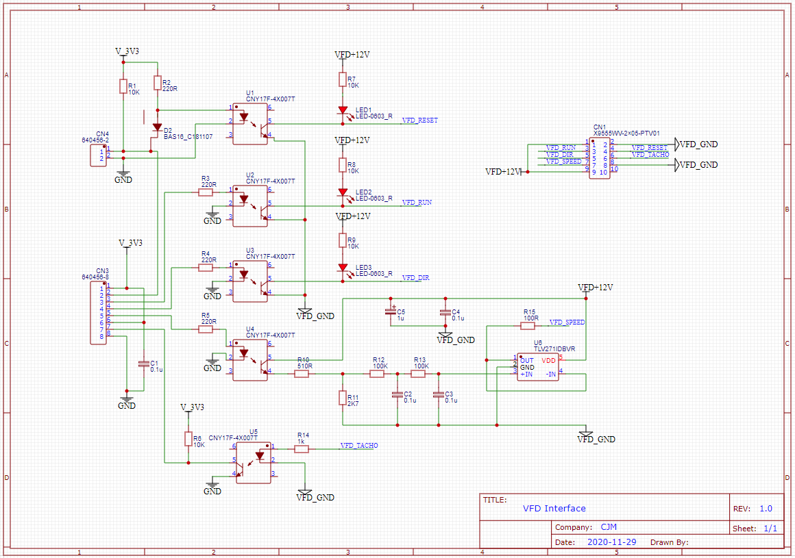
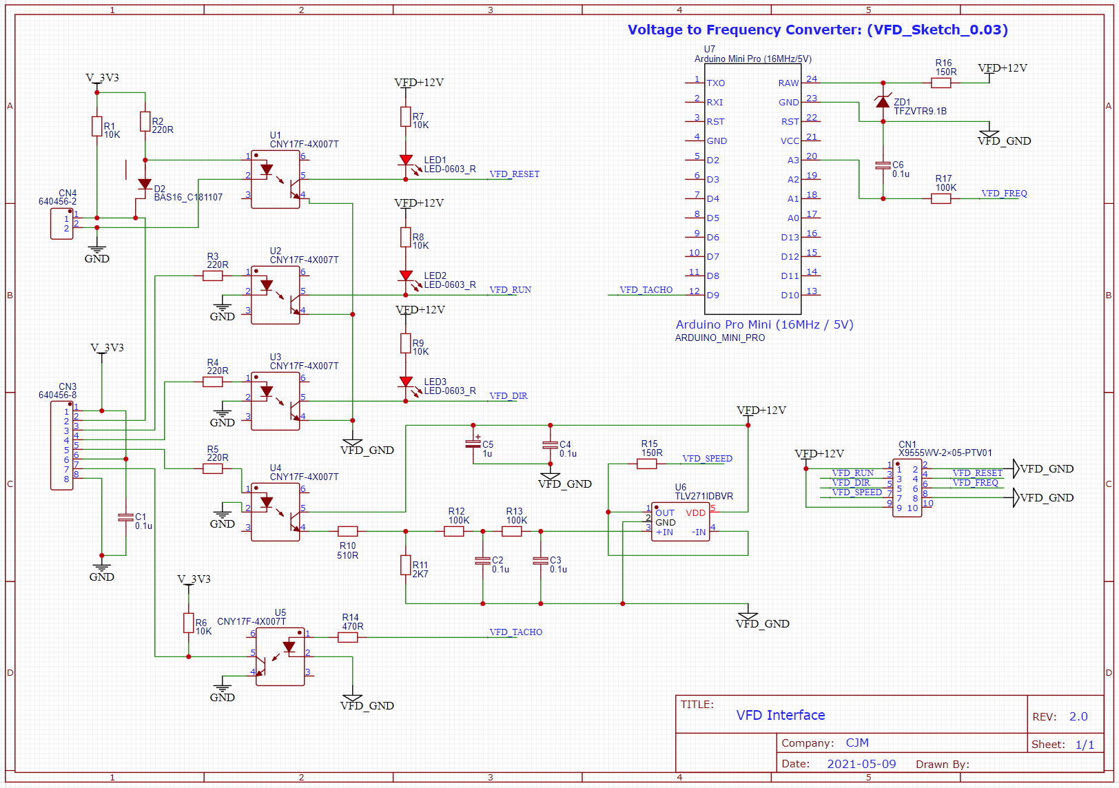
      A) VFDs generally require higher control voltages than the Duet outputs provide, so some extra circuitry (e.g relays or opto-isolators) is needed to match the Duet control outputs to the VFD inputs

      B) Some VFDs have FWD and REV inputs instead of RUN and DIR inputs. In my case (an “AskPower” unit from eBay) I found that wiring RUN -> FWD and DIR -> REV worked fine. However, this may not be a universal solution.

      Edit 7/8/2021 - Closing quotation marks corrected - thanks to @Wurke for spotting this.

      posted in CNC
      cjmundefined
      cjm
    • RE: Slow down before endstop?

      @sinned6915 The suggestion of using a mode 1 Z-probe certainly sounds an interesting solution.

      However, are we absolutely certain that it does give a controlled deceleration, rather than just forcing a stop like all the other Z-probe options?

      I ask because this appears to be an undocumented feature, although I might well have misread the Duet dictionary!

      posted in CNC
      cjmundefined
      cjm
    • RE: CNC Spindle Speed Monitoring and Control

      @educatingsavvas Yes, indeed.
      You might be interested in the most recent post in here:
      https://forum.duet3d.com/topic/19968/duet-integration-with-an-askpower-a131-vfd
      This explains a way to convert the VFD analogue output voltage into a tacho pulse whose frequency is proportional to the spindle speed.

      This frequency can be easily read by one of the fan tacho inputs on a Duet, using an opto isolator to keep the VFD interface electrically isolated from the Duet.

      So, if M950 allowed a spindle tacho input and scale factor to be defined the Duet could use this to display actual spindle RPM and the other things suggested above like waiting after M3/M4 for the spindle to have got up to speed.

      posted in Firmware wishlist
      cjmundefined
      cjm
    • RE: VFD integration: M3, M4, M5 Macros and RPM measurement

      As an addendum, having had more time to explore the depths of this forum I realise I’m playing catch-up and see that similar concepts were discussed during the genesis of CNC mode: e.g.

      https://forum.duet3d.com/topic/1662/running-gcode-cnc-on-duet-wifi?_=1596960514625

      Nonetheless, I’d still like to suggest M3/4/5 macros as, to my mind, controlling the VFD/spindle is machine specific and so is analogous to homing, where the RRF “g-code for everything philosophy”, as implemented through the home all.g and related macros, is simple and works to great effect.

      Whilst it’s also possible to implement the extra spindle machine specific commands by modifying each CAM post processor, this seems a backward step as otherwise the simple M3/4/5 are universal across different CAM applications.

      Anyway, just my ha’pennies worth...

      posted in CNC
      cjmundefined
      cjm

    Latest posts made by cjm

    • RE: Reprap firmware with cnc... what free cam software?

      @breed I find CAMBAM works well for me:

      https://cambamcnc.com

      There’s a decent free evaluation period. If you are only doing small jobs (<1000 lines of gcode) I believe you can continue to use it for free. If you find it suits your needs then it’s not too expensive (£93 one off charge).

      I’ve found the documentation clear and the forum helpful.

      posted in CNC
      cjmundefined
      cjm
    • RE: Duet3 as hardware for LinuxCNC?

      @roiki11 Thanks very much for the explanation - helps me to understand better!

      posted in CNC
      cjmundefined
      cjm
    • RE: Duet3 as hardware for LinuxCNC?

      @rjenkinsgb Apologies for a NOOB question but as many CAM programs seem capable of generating effective tool paths without requiring the G40,G41,G42 tool path offsets, what benefit does having them bring?

      posted in CNC
      cjmundefined
      cjm
    • RE: PWM Issues

      @jvp79 Good news!

      posted in CNC
      cjmundefined
      cjm
    • RE: PWM Issues

      @jvp79 Hmmmh...

      Your measurements indicate the converter is connected and being powered correctly so what else would stop it working?

      Perhaps the PWM frequency is outside of the range of the converter? Looking at the Ooznest instructions I see the following command is used to configure the PWM:

      M950 R0 C"e0heat" L0:25000 Q100

      This sets the PWM frequency to 100Hz, whereas the quoted minimum frequency for the converter is 1KHz, so perhaps try adding an extra zero to set the PWM frequency to 1KHz like so:

      M950 R0 C"e0heat" L0:25000 Q1000

      Otherwise, it sounds as though the converter might be faulty...

      posted in CNC
      cjmundefined
      cjm
    • RE: PWM Issues

      @jvp79 Just as a sanity check, you're seeing + (positive) 24V and not - (negative) 24V?

      posted in CNC
      cjmundefined
      cjm
    • RE: PWM Issues

      @jvp79 It’s probably worth using your multimeter to check the voltage between pin 3 (multimeter red lead) and pin 4 (multimeter black lead) of the PWM module.

      With the power on, this should read +24V.

      posted in CNC
      cjmundefined
      cjm
    • RE: M669 S and T values

      @dc42 Thanks for clarifying the M669 reporting of S and T.

      There has been some discussion of setting S and T to small values, so that the time delay and distance moved after a pause command can be reduced.

      I wondered whether you be able to explain a little more about any trade offs as S and T are reduced ?

      posted in Tuning and tweaking
      cjmundefined
      cjm
    • RE: M669 S and T values

      @droftarts It appears that M669 doesn’t report the S and T values? This is my console output:

      26/11/2021, 21:11:46: Connected to 192.168.0.9
      26/11/2021, 21:12:19: M669 S0.001
      26/11/2021, 21:12:32: M669: Kinematics is Cartesian, matrix:
      1.00 0 0
      0 1.00 0
      0 0 1.00
      26/11/2021, 21:12:46: M669 S1.0
      26/11/2021, 21:12:52: M669: Kinematics is Cartesian, matrix:
      1.00 0 0
      0 1.00 0
      0 0 1.00
      26/11/2021, 21:14:17: M669 S1.0 T1.0
      26/11/2021, 21:14:27: M669: Kinematics is Cartesian, matrix:
      1.00 0 0
      0 1.00 0
      0 0 1.00
      
      
      posted in Tuning and tweaking
      cjmundefined
      cjm
    • RE: M669 S and T values

      @droftarts Thanks, Ian. Will have a go this weekend…

      posted in Tuning and tweaking
      cjmundefined
      cjm