Coupled polar kinematics
-
achrn said (inter alia) in Coupled polar kinematics:
In PolarKinematics::CartesianToMotorSteps add crosstalk effect (and change the order of calculation, as discussed above):
This (and MotorStepsToCartesian) turns out to be not as simple as I hoped, and with a little thought it becomes apparent why - with the coupling between X and Y axes, there is no 1:1 mapping between the machine target position and a set of motor positions. With radial position controlled by a shaft coaxial to the turntable, the 'motorPos' X axis (radial distance) depends upon whether that position is reached turning clockwise or anticlockwise. Mostly this works out OK, but my code (up the thread) doesn't work when you cross the line where the atan2 function swaps (i.e. +/- 180 degrees).
That is, if I'm at position [-100,1] and want to move to [-100,-1], the correct path is obviously (to a human) 2mm long and features a small change in angle and no change in radius, but the firmware
CartesianToMotorSteps()function has no concept of path, and moving from 100 radius at 179.9 degrees to 100 radius at -179.9 degrees, is 359.8 degrees of rotation, which (with the coupling I have) would require a pretty big shift in radial motor position. The firmware does know the angle is a continuous rotation axis and handles that OK, but my code doesn't know that this apparent 359.8 degree change is not actually a big rotation, and tries to introduce a big and instantaneous change to radial position as it crosses the line.I haven't figured out a solution to this. I'm slightly nervous that a rigorous solution doesn't exist (because of the structure of the kinematics functions) - I think that might need a
CartesianToMotorStepsthat has as input not only where it needs to be but also where it's coming from. However, I need to delve more into how the firmware handles a continuous rotation axis and factor something similar into the radial axis (i.e. the code does know that it can rotate from -179.9 degrees to 179.9 degrees by rotating -0.2 degrees not +359.8 degrees, I need to tell it that while actually rotating +359.8 degrees requires a large change in radial position motor, this move doesn't need that change).So mostly I'm just posting to close off the possibility that anyone searching in future finds my previous post and believes it - don't believe it, it's more complex than that suggests.
-
@achrn you could try to avoid big angle changes by storing the planned complete move and make sure when calcuation of the segments occur, that there are no big angle changes. Your problem is similar to kinematics where we have multiple inverse solutions for a given forward kinematics. Then the solution can be taken which is nearest to the segmented moves before on the path.
To avoid changes in separate firmware code, I stored the path when LimitPosition is called, which is called at the beginning of a new move. LimitPosition has initialCoords and finalCoords for G0/G1 moves and finalCoords for G2/G2 moves. For G2/G3 the finalCoords values of the move before should be stored as new starting position.
The motorPos are int32_t values, so there are some float-int conversions in the code above which I would avoid.
-
@joergs5 said in Coupled polar kinematics:
make sure when calcuation of the segments occur, that there are no big angle changes.
I think this is the bit I need to find in the code. Since it is segmenting the path, I should be able to identify when something is wrapping around, i.e. in a segmented path, there shouldn't be a segment where angle changes by nearly 360 degrees. (But there could be a 180 degree change - e.g. from [0.99,0.01] to [-0.99,-0.01] is a 2mm long segment that features a 180 degree rotation).
Thanks for the pointers.
-
@achrn
I think you have to change the CartesianToMotorSteps motorPos values when the described situation arises. The solution is, to set motorPos[1] to a value less (or more) one full rotation value. For analysis, the M114 Count values can be used, which are the motorPos values.
The minimum and maximum values of motorPos should probably be limited to avoid wire or filament break (wires of heated bed e. g.). -
@joergs5 said in Coupled polar kinematics:
The minimum and maximum values of motorPos should probably be limited to avoid wire or filament break (wires of heated bed e. g.).
No wires - the radial and angular position are of the effector, and bed is stationary. There's also no material fed across the movement interface - it's effectively a pen plotter. Thus it is a genuinely continuous rotation bed.
(The first limit is motor steps counter stored in a 32 bit variable, which gives me 'only' about 26 hours of continuous one-way rotation. I don't anticipate exceding that limit, however dc42 advises that G92 will reset the steps counter, so some gcode can overcome that 'limit'.)
-
@achrn said in Coupled polar kinematics:
the radial and angular position are of the effector, and bed is stationary.
How about linking an encoder to the rotary axis - eg. via a 1:1 timing belt drive - and using closed loop control for the radial position, with that encoder as the feedback?
It should cause the radial motor to track and inherently compensate the angular motion?
-
@achrn said in Coupled polar kinematics:
No wires - the radial and angular position are of the effector, and bed is stationary.
So there will be no problem to implement the proposed change to the code.
One could use brushes (or pogo pins) to implement continuous heated roting plates if needed.
-
@achrn I think the reason is the jump of the atan2 function at 0 from pi (180 degrees) to -pi if x < 0, please see https://en.m.wikipedia.org/wiki/Atan2. x=0 is not defined for atan2.
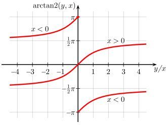
I would propose to store an absolute counter (how many full rotations are made) and caching the motorPos of last move, so instead of the big change, a small one with one rotation more/less can be made. The absolute counter is not important for your indefinite rotation plate, but for those who have to rewind. The 180 degree positions can be calculated from the M92 values, because M92*180 (and *(360+180), *(-360+180) etc.) are the 180 degree positions.
-
@rjenkinsgb said in Coupled polar kinematics:
How about linking an encoder to the rotary axis - eg. via a 1:1 timing belt drive - and using closed loop control for the radial position, with that encoder as the feedback?
It should cause the radial motor to track and inherently compensate the angular motion?
I can see how it would work (in principle), but I fear it would be more complicated than getting the code to determine when it is jumping and doesn't need the implied radial position adjustment. Also, I'm endeavouring to avoid wires across the rotating interface, and the encoder tracking radial position is the 'otehr side' of that interface, so would need to signal across it. At the moment I'm using stall detection to home the radial axis and it's purely coaxial mechanical elements across the rotating interface.
@joergs5 said in Coupled polar kinematics:
I think the reason is the jump of the atan2 function at 0 from pi (180 degrees) to -pi if x < 0, please see https://en.m.wikipedia.org/wiki/Atan2. x=0 is not defined for atan2.
Yes, I'm sure that's the cause of the jump (as the mechanism moves through that location the stepper driving the radial position chirps / screams / jumps - I think it basically just gets hit with an instantaneous demand to turn one whole revolution because it 'thinks' the angular position has turned one whole revolution). I need to look at the code more closely, or more accurately, look at more of the code (than just the two functions CartesianToMotorSteps and MotorStepsToCartesian) to work it out.
Thanks all.
-
@achrn said in Coupled polar kinematics:
Also, I'm endeavouring to avoid wires across the rotating interface, and the encoder tracking radial position is the 'otehr side' of that interface
?? The encoder would be fixed, probably near the rotation drive motor - it's to measure the rotary position, not radial, even though it's to add in to the radial drive position to counter the rotational influence.
Another alternative setup would be to use a differential (ie. like a vehicle axle type) to combine the rotation with the radial feed.
That's done with machine tools (horizontal borers) to control the radial position of the tool slide on a rotary facing heat, as that otherwise has the same problem.
Other complications & hardware vs software are a different matter and are all down to you, I'm just throwing in ideas..
-
@rjenkinsgb said in Coupled polar kinematics:
@achrn said in Coupled polar kinematics:
Also, I'm endeavouring to avoid wires across the rotating interface, and the encoder tracking radial position is the 'otehr side' of that interface
?? The encoder would be fixed, probably near the rotation drive motor - it's to measure the rotary position, not radial, even though it's to add in to the radial drive position to counter the rotational influence.
Sorry, yes you're right. I had it swapped round in my mind.
I also hadn't thought about a purely mechanical solution - that has some attraction. Thanks.
-
@achrn said in Coupled polar kinematics:
With radial position controlled by a shaft coaxial to the turntable, the 'motorPos' X axis (radial distance) depends upon whether that position is reached turning clockwise or anticlockwise. Mostly this works out OK, but my code (up the thread) doesn't work when you cross the line where the atan2 function swaps (i.e. +/- 180 degrees).
To me, the obvious solution is to disable continuous rotation when the crosstalk factor is nonzero. However, that means that you won't be able to print in a small sector of the bed.