Duet3D Logo Duet3D
    • Tags
    • Documentation
    • Order
    • Register
    • Login
    1. Home
    2. rjenkinsgb
    • Profile
    • Following 0
    • Followers 1
    • Topics 13
    • Posts 435
    • Best 87
    • Controversial 0
    • Groups 0

    rjenkinsgb

    @rjenkinsgb

    Professional electronics designer & programmer for several decades, interested in electronics, computers, music & just about any kind of technology.

    105
    Reputation
    54
    Profile views
    435
    Posts
    1
    Followers
    0
    Following
    Joined Last Online
    Location Sheffield, England

    rjenkinsgb Unfollow Follow

    Best posts made by rjenkinsgb

    • Meet the Frankentron

      This is my very heavily modified machine, which started as a Tronxy X5SA Pro.

      The head carriage is totally replaced with a wider version based around a machined 8mm aluminium plate that has space for an E3D toolchange system between the slideway bearing mounts.

      That has a printed "cap" which has the anchor clamps for the belts built in to it, plus channels for the various cables, mount points for the X limit and a BLTouch probe, with slots to take captive nuts for the various retaining screws.

      (The cable end anchors etc. and cable support strips are the E3D ones.)

      The Z drives are independent and all endstop switches are now optical.

      The toolholders are mounted on bases fitted to the rear (originally front) extrusion, and to make space above that the drive belt idler pulleys are relocated back by 34mm using short sections of extrusion fitted on spacers, so the original idler mount locating screw position is now in line with the cross extrusion mounting screw.

      The Duet 6HC board is in an aluminium enclosure in the base, at present just resting in place. There is clearance to add a couple of thin rails across the frame to mount it on, and the PSU will probably go on a side extrusion.

      There is a tool distribution board in a plastic box on the rear of the frame, and toolboard cables plug in to that - or a dummy plug can be fitted to bypass the CAN chain if one is removed.

      The tools are, right to left:
      V6 bowden with hardened nozzle and hemera extruder, to allow for carbon filled materials.
      V6 bowden using the original tronxy titan extruder for general use.
      Hemera direct, to allow for flexible materials
      Plus a part build E3D ASMBL.

      I'm still spending more time doing fine adjustments than printing so far; the original bed had quite a significant sag in the middle, between its support rails, so I have added a glass bed over that which has given a great improvement, but still a slight cornerways tilt I'm trying to adjust out.

      All the modifications are plug-in or bolt-on, the machine can be completely restored to its original specification. It has lost a bit more printing area than I originally expected, but still a lot bigger than my Overlord Pro.

      The entire setup could be moved to or used on one of the larger TronXY machines, eg. a 500 or possibly a 600, if the head slide uses the same rail section.

      If anyone wants more details of the head mods or the files for those, or any other info about it, let me know.

      IMG_5271.JPEG

      IMG_5280.JPEG

      IMG_5273.jpg

      IMG_5270.jpg

      IMG_5279.JPEG

      IMG_5276.JPEG

      IMG_5281.jpg

      posted in My Duet controlled machine
      rjenkinsgbundefined
      rjenkinsgb
    • RE: CAN Latency and practical application

      As far as I am aware, the CAN latency only affected such as "instantaneous" signals between two boards, like an axis limit or probe on one board relating to an axis motor on a different board.

      In normal operation, all commands are queued ahead of time and then executed synchronously by all boards.

      That's what caused a problem with a switch/probe detection, as the motor board would still be executing the move for a few milliseconds before the probe signal reached it.

      I believe even that is now a non-issue, and the axis will take the correct position from the switch trigger point.

      Even without that, a simple solution is a two stage home, backing off a fraction then a very slow move on to the switch again, so the distance moved during any delay is irrelevant.

      posted in Using Duet Controllers
      rjenkinsgbundefined
      rjenkinsgb
    • RE: Open-loop for performance, closed-loop for error recovery.

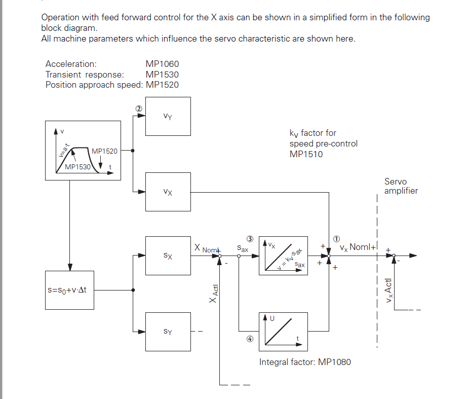
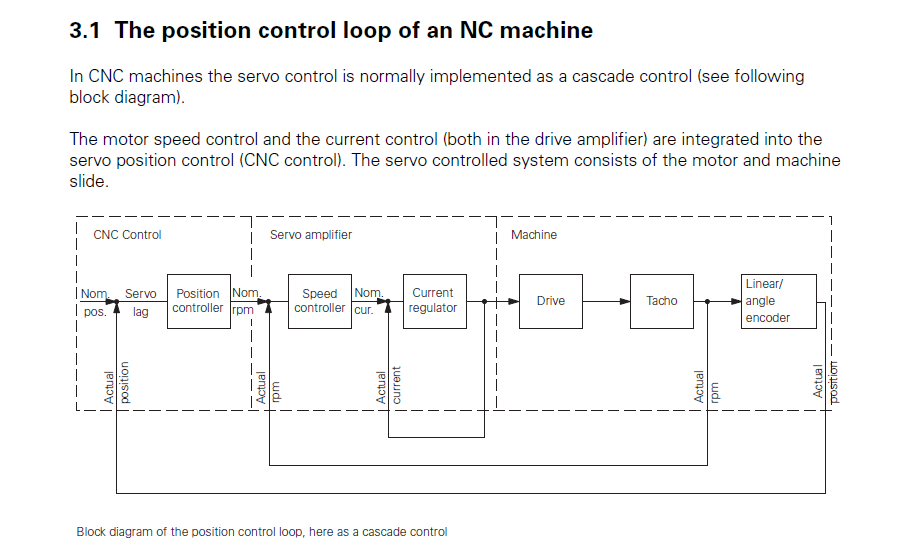
      This is the other info I was thinking of, from a 1980s system with separate, analog servo drives.

      The lookahead / PID is probably easier to replicate from this version:

      Servo_Feedforward.png

      That's the CNC section of this overall drive system diagram:

      ServoLoops.png

      The control those diagrams relate to (Heidenhain TNC360) runs everything on a 16MHz MC68000 if I remember correctly, for machines operating with multi-axis interpolation and contouring at accuracies down to microns, but with totally separate servo drives.

      posted in Hardware dev
      rjenkinsgbundefined
      rjenkinsgb
    • RE: Smert effector tilting during bed leveling and print

      @lildannyoso
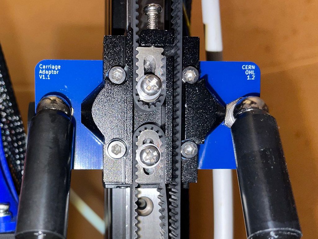
      Looking at the video, you don't appear to be using the Smart Effector PCB adapters on the vertical rail carriages?

      SmartEffectorAdapter_sm.jpg

      A delta printer mechanism relies on each pair of rods always being absolutely parallel.

      If there is even the slightest difference, a fraction of a millimetre, in joint spacing between the two ends of the link arms/rods, the overall geometry of the machine will be wrong and the effector will tilt.

      That's why you get the adapters in the kit, to guarantee correct spacing at both ends of the arms.

      They can be on top of or sandwiched in a printed carriage, but those need to be what define the rod spacing.

      posted in Smart effector for delta printers
      rjenkinsgbundefined
      rjenkinsgb
    • RE: Wiring and programming a switch for a conditional statement

      You can use a simple conditional statement, something like this:

      if sensors.gpIn[3].value = 0
              G91
              G1 Z15
              G90
      

      Use whichever input pin and level is appropriate for the switch.
      Any following indented lines will only be executed if the conditional statement is true. Normal execution continues with the first non-indented line.

      posted in Gcode meta commands
      rjenkinsgbundefined
      rjenkinsgb
    • RE: DWC Tool #s not lining up with Temp Chart

      There is no extruder defined in the tool, and two fans; is that confusing things?

      Try this?

      ; Tools
      M563 P0 S"DeltaEffector" D0 H1 F0                  ; define tool 1 with heater 0 and Fan 0
      G10 P0 X0 Y0 Z0                                    ; set tool 0 axis offsets
      G10 P0 R25 S125                                    ; Active 125 Standby 25 
      

      That sequence sets up tool 0 OK on my multi-tool machine.

      posted in Duet Web Control
      rjenkinsgbundefined
      rjenkinsgb
    • RE: Duet3 as hardware for LinuxCNC?

      @dc42 said in Duet3 as hardware for LinuxCNC?:

      can you explain #1 in more detail? Why do you need it, and how would you set the acceleration/deceleration profiles?

      I suspect he means the ability to adjust tool path speed & acceleration rather than just axis speed?

      eg. for one example:
      Milling into an internal corner of a pocket, the speed on the existing path has to slow down dramatically before the cutter buries itself in the wall it's going to start moving along after the change in direction, so the cutter is not overloaded.

      With an external corner the load drops off as it reaches the end of the move on that axis and starts along the next side, so it does not need to slow down in the same way. The path at that point would also follow a small radius so the cutter "rolls around" the corner position.

      Those behaviours depend on the tool offset being either left or right of tool path and the direction of the corner.

      The Duet does not have tool path offsets at all, as far as I am aware?
      (G40/41/42)
      They are normally also used with a separate editable tool geometry table; at minimum, length from the toolholder or chuck and diameter .

      I just do not know how practical it is to try and duplicate serious (high force in proportion to drive capability) milling type axis control on a controller such as a Duet, based around stepper motors?

      CNC axes have to compensate for both the direct load of "pushing" a tool in to a workpiece, and the reaction force of a rotating cutter trying to push sideways to the feed direction, affecting other axes.

      Industrial CNCs use axis drives with torque feedback as the lowest level of the axis control loop; the velocity loop in turn controls torque, and the position loop controls velocity.
      (Plus a kind of PID system that takes inputs from different stages of the overall axis system).

      Is that torque control stage possible with the motor drivers used on the Duet boards?

      I can't see it working properly at all with the external closed loop driver modules, as the CNC does not not have axis position feedback with those, at present; the most critical feedback loop, for actual position, is open.

      An axis add-on board that also has an analog setpoint output, for use with larger external servo drives, and with differential ABZ quadrature position feedback, plus a good set of non dedicated 24V I/O connections could be a more practical alternative.

      The ABZ feedback is because precision CNCs do not use switches directly as home positions - the switch is just to tell the CNC/PLC that the feedback device is in the correct rotation or cycle for it to look at the Z pulse from the encoder or scale and pick up the precise position from that. And differential to avoid interference on longer cable runs and with higher current motors in use.

      Also display - continuous "live" axis position, feedrate, distance to go & spindle speed, with active M code and G code status plus override percentages.

      All serious industrial CNCs also have an integrated PLC of some I/O size, to handle the machine mechanics, with the CNC only directly interfacing with the axes drives and estop, and all other hardware signals being passed between the CNC side and PLC side as virtual I/O in memory and then handled via the PLC program and PLC controlled I/O to adapt to the specific machine hardware.

      Note that I'm not criticising Duet boards or Reprap firmware; for what they are designed for, they are superb.

      It's just that having worked with large machine tools for 40+ years (and written a CNC system from scratch back in the 80s) there is simply so much that is radically different in controlling a machine tool compared to a 3D printer, it seems to me that the two should be each based on dedicated firmware (and possibly hardware) rather than trying to pack everything for both types of system into a single program & ending up with a jack of all trades but master of none result.

      The Duet CPUs are orders of magnitude faster and more capable than a lot of older CNCs that can do high speed micron precision contour machining, but the machine and drive interfaces are just not there at present, for anything much above "desktop" size machines.

      For an example of what I'd consider the minimal capabilities for a "perfect" small CNC system, have a look at the Heidenhain TNC360 from the early 1990s; that has everything needed, without the bells & whistles and excess complexities of newer controls.
      (Ignore the graphics & non G code programming capabilities etc., they are not relevant to the machine control side).

      posted in CNC
      rjenkinsgbundefined
      rjenkinsgb
    • RE: Connection issues between 6HC and Pi 3B

      @alastair1
      Make sure you use "run as administrator" when starting Balena Etcher on windows.

      It may fail otherwise.

      posted in General Discussion
      rjenkinsgbundefined
      rjenkinsgb
    • RE: Polar Coordinates

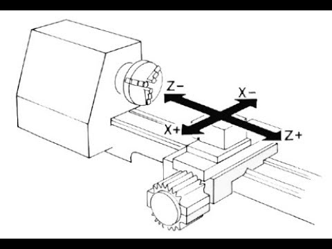
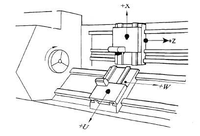
      The convention for lathes and vertical borers is that the spindle axis is Z and the radial axis is X. There is no Y axis.

      With two tools, the second tool movement parallel to Z is W and parallel to X is U.

      If you use the spindle / chuck for rotary positioning, then the angular setting is normally C axis

      If you want to keep compatibility with commercial machines, I'd suggest staying with those axis names.

      Lathe_Single.png

      Lathe_Twin.jpg

      posted in Using Duet Controllers
      rjenkinsgbundefined
      rjenkinsgb
    • RE: Direction/Velocity Vector of Printhead movement

      @deme said in Direction/Velocity Vector of Printhead movement:

      looking for a way to be able to read the feed direction from the printer controller.

      Could you use an accelerometer on the tool?
      That would give instantaneous direction & acceleration ( so indirectly, velocity).

      The Duet can also take an accelerometer directly, though I'm not sure if the data that collects can be accessed.

      posted in Plugins for DWC and DSF
      rjenkinsgbundefined
      rjenkinsgb

    Latest posts made by rjenkinsgb

    • RE: Help please - Strange and sudden axis fault on Kossel XL

      @dc42 Problem solved, thank you!

      I'd already checked for any slip or backlash by holding the belt while jogging small amounts, but was going to double-check the grub screws to be certain.
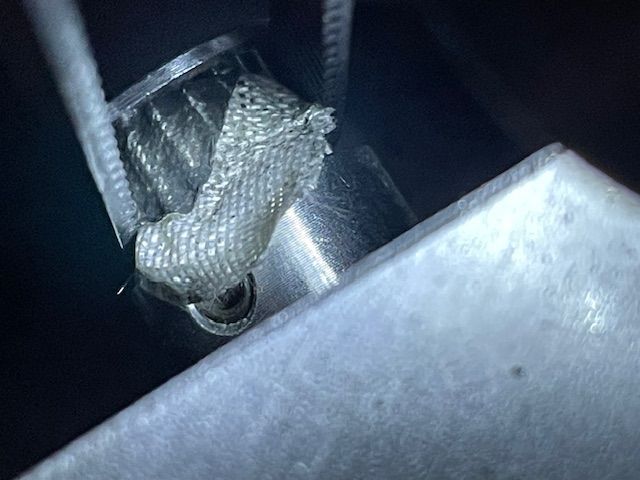
      They need a torch to see them clearly.

      They are OK - but I was not expecting the pulley to have changed size!
      A small fragment of fibre reinforced tape from somewhere was stuck on it, so the belt was moving slightly further for each motor rotation.

      IMG_4393.jpg

      posted in General Discussion
      rjenkinsgbundefined
      rjenkinsgb
    • RE: Help please - Strange and sudden axis fault on Kossel XL

      @dc42 No, just generic fibre reinforced ones.

      posted in General Discussion
      rjenkinsgbundefined
      rjenkinsgb
    • Help please - Strange and sudden axis fault on Kossel XL

      Hi,
      My Kossel XL has been working fine for the last couple of years.
      (Duet 3 MB6HC; firmware 3.4.0).

      I've not used it for a couple of months (too busy with work).

      I just tried to print something and found that one axis is moving around 10% further than the other two - when it went to probe the bed centre, it was a long way off to the side.

      Homing then jogging Z- shows the same effect - the front left axis (as I have it positioned) moves proportionally too far as it travels down, and the same jogging back up - so all three level gradually level out again as it gets back to the top!

      I've checked the config file is not corrupt; all three axis parameters are identical.
      Also tried power off and let it restart without attempting to print, no difference.

      The motor pulleys and belts are all fine, no slipping.

      Any ideas?

      Thanks,
      Robert.

      posted in General Discussion duet 6hc delta axis problem
      rjenkinsgbundefined
      rjenkinsgb
    • RE: Angled Printing on Delta Printer

      What happens if you jog Z over the full height range - does the nozzle move purely vertical or have a lateral offset with height??

      It's not likely, but the only things I can think of are a stepper with a different physical step count, or a pulley with a different size?

      posted in General Discussion
      rjenkinsgbundefined
      rjenkinsgb
    • RE: Anybody wants a stepper motor analyzer?

      @Th0mpy said in Anybody wants a stepper motor analyzer?:

      You can update your code to point to these two repositories:

      That's got it working, thank you!

      posted in General Discussion
      rjenkinsgbundefined
      rjenkinsgb
    • RE: Printbrite+ ? Has anyone any experience with this?

      @dc42
      OK thanks, I was using 70'C, that may be the problem!

      I'll try it at 80'C

      posted in General Discussion
      rjenkinsgbundefined
      rjenkinsgb
    • Printbrite+ ? Has anyone any experience with this?

      My Kossel XL has been working very well until about a week ago, when a PETG print lifted a layer of glass out of the bed, despite a fresh coat of bonding/release spray before each print...

      I had ordered some Printbrite+ during lockdown, which arrived a few month back but I did not do anything with it.

      Glass bed turned over, printbrite applied, all cleaning & curing instructions followed carefully.

      The first print I tried broke loose after a couple of layers.. I re-read the instructions & realised I'd done the pre-print clean with acetone, instead of soapy water. Try again, pre-clean with soapy water and it worked as advertised!
      Three or four prints, all OK, just releasing once the bed started to cool.

      Then I set up a large area 12 hour print, same clean - and it broke loose in the middle of the night & wasted the lot.

      I'm not sure if I'm doing something wrong with it, or it's just an unreasonably critical surface??

      Any ideas? I have things I want to print but don't want to waste masses of filament if its going to be hit & miss on which stay attached to the bed.

      (I have a new 300mm diameter Borosilicate bed on order just in case).

      posted in General Discussion bed adesion printbrite
      rjenkinsgbundefined
      rjenkinsgb
    • RE: Anybody wants a stepper motor analyzer?

      @Th0mpy
      Excellent, thank you

      posted in General Discussion
      rjenkinsgbundefined
      rjenkinsgb
    • RE: Filament Drying

      I just use large zip bags to store each open reel, with a fabric bag of silica gel sealed in with the reel.

      I also use a Sunlu dryer as the filament feed while printing.
      (one of these types -
      https://www.amazon.co.uk/SUNLU-Filament-Printing-Dimensional-Accuracy/dp/B081ZLG6KR )

      posted in 3D Printing General Chat
      rjenkinsgbundefined
      rjenkinsgb
    • RE: Anybody wants a stepper motor analyzer?

      @zapta
      Hi,
      OK, thanks for that, hopefully Th0mpy is around!

      I can't find anything relevant in his posts in this topic, unfortunately.

      posted in General Discussion
      rjenkinsgbundefined
      rjenkinsgb