Duet3D Logo Duet3D
    • Tags
    • Documentation
    • Order
    • Register
    • Login

    Mini5 to 1LC to smart effector wiring and control

    Scheduled Pinned Locked Moved
    Duet Hardware and wiring
    4
    38
    1.4k
    Loading More Posts
    • Oldest to Newest
    • Newest to Oldest
    • Most Votes
    Reply
    • Reply as topic
    Log in to reply
    This topic has been deleted. Only users with topic management privileges can see it.
    • jay_s_ukundefined
      jay_s_uk @opentoideas
      last edited by jay_s_uk

      @opentoideas
      Screenshot_20211127-182214.png
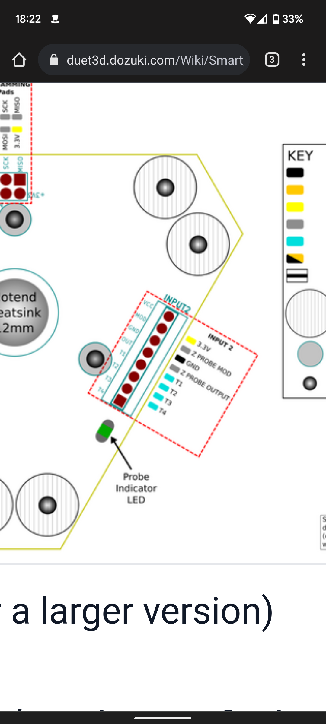
      The probe gets it's power from here. I.e. the 3.3v (which can also be 5v) and, the output to the IO input and ground to ground
      That will get the green led working. You can use an IO for these.
      The heater goes to out0 and the fans to out1 and out2.
      Thermistor obviously to the temp input

      Owns various duet boards and is the main wiki maintainer for the Teamgloomy LPC/STM32 port of RRF. Assume I'm running whatever the latest beta/stable build is

      opentoideasundefined 1 Reply Last reply Reply Quote 1
      • opentoideasundefined
        opentoideas @jay_s_uk
        last edited by

        @jay_s_uk the ground on pin 6 was in the wrong way round not making contact with the pin so its powering up now.

        been taking care with every pin but still got one wrong.

        off to try and map things from here thank you

        jay_s_ukundefined 1 Reply Last reply Reply Quote 1
        • jay_s_ukundefined
          jay_s_uk @opentoideas
          last edited by

          @opentoideas ask if you need anything else

          Owns various duet boards and is the main wiki maintainer for the Teamgloomy LPC/STM32 port of RRF. Assume I'm running whatever the latest beta/stable build is

          opentoideasundefined 1 Reply Last reply Reply Quote 0
          • opentoideasundefined
            opentoideas @jay_s_uk
            last edited by

            @jay_s_uk thanks, stopping for tonight but just going to work the basics one bit at a time until everything is connected hopefully it will be plain sailing from here....

            1 Reply Last reply Reply Quote 1
            • A Former User?
              A Former User @jay_s_uk
              last edited by A Former User

              This post is deleted!
              1 Reply Last reply Reply Quote 0
              • opentoideasundefined
                opentoideas
                last edited by opentoideas

                well it looks like the Duet continues to be smarter than me!

                I have been trying to define the hotend thermometer in my config.g without any luck however having a look in the object model tab the duet can see and correctly read the connected thermometer.

                Selected node: sensors.analog[0].lastReading is providing the thermostat and I have confirmed its correct how do I assign this as the hotend?

                ohh ok looks like the config tool makes life much simpler lol

                A Former User? 1 Reply Last reply Reply Quote 0
                • A Former User?
                  A Former User @opentoideas
                  last edited by A Former User

                  This post is deleted!
                  opentoideasundefined 1 Reply Last reply Reply Quote 0
                  • opentoideasundefined
                    opentoideas @A Former User
                    last edited by opentoideas

                    @arnold_r_clark thank you, forgot the probe was a PT1000 thats working now....

                    Touch probe is my next hiccup

                    ; Z-Probe
                    M558 P8 R0.4 C"20.io0.in+20.io0.out" H5 F1200 T6000 ; set Z probe type to effector and the dive height + speeds
                    G31 P100 X0 Y0 Z-0.1                                    ; set Z probe trigger value, offset and trigger height
                    M557 R85 S20                                          ; define mesh grid


                    working through the commissioning on the dozuki and at the part where a G31 should return a zero value however I get "invalid Z probe index"

                    @jay_s_uk any thoughts?

                    This is the last problem now as everything else is tested and working🙈👍🍻

                    A Former User? jay_s_ukundefined 2 Replies Last reply Reply Quote 0
                    • A Former User?
                      A Former User @opentoideas
                      last edited by A Former User

                      This post is deleted!
                      opentoideasundefined 1 Reply Last reply Reply Quote 0
                      • opentoideasundefined
                        opentoideas @A Former User
                        last edited by opentoideas

                        @arnold_r_clark

                        well I was working from the instructions and config tool and both used the control and mod pins - found a post from DC42 referencing the need for the second pin if you wanted to adjust sensitivity but should work without it.

                        either way changing my M558 to only reference 20.io0.in still gives the same error though it does add "z probe" to the dasboard but not responding

                        I have had plenty of head crashes in the past so when it comes to the Z probe I make sure it works before commanding any movement.

                        the only references I have found to index is with multiple probes and there is an optional K parameter to M558 but tried adding K1 with no change.

                        without any references to what this error means I am struggling

                        1 Reply Last reply Reply Quote 0
                        • jay_s_ukundefined
                          jay_s_uk @opentoideas
                          last edited by

                          @opentoideas your M558 line should be this
                          M558 P8 R0.4 C"20.io0.in+io0.out" H5 F1200 T6000 note the removal of the 20. in the middle.
                          Can you post your full config and the actual wording on the error?

                          Owns various duet boards and is the main wiki maintainer for the Teamgloomy LPC/STM32 port of RRF. Assume I'm running whatever the latest beta/stable build is

                          opentoideasundefined 1 Reply Last reply Reply Quote 0
                          • opentoideasundefined
                            opentoideas @jay_s_uk
                            last edited by opentoideas

                            @jay_s_uk @Arnold_R_Clark

                            must have been syntax as I thought mine and Arnold were the same but a copy and paste and it now works - not sure where the difference was but its running.

                            Jay I tried your M558 back to the error :

                            Error: G31: Invalid Z probe index

                            flip side without the second pin reference when I try to reduce the sensitivity....

                            M672 S105:020:235
                            Error: M672: Programming remote Z probes not supported

                            so with a single pin reference it works but the contact is far to hard and I seem unable to reduce the sensitivity

                            full config.g :

                            
                            ; Configuration file for Duet 3 Mini 5+ (firmware version 3.3)
                            ; executed by the firmware on start-up
                            ;
                            ; generated by RepRapFirmware Configuration Tool v3.3.10 on Sun Nov 28 2021 15:18:17 GMT+0000 (Greenwich Mean Time)
                            
                            ; General preferences
                            G90                                                   ; send absolute coordinates...
                            M83                                                   ; ...but relative extruder moves
                            M550 P"Predator"                                      ; set printer name
                            M665 R227 L440 B185 H450                            ; Set delta radius, diagonal rod length, printable radius and homed height
                            M666 X0 Y0 Z0                                         ; put your endstop adjustments here, or let auto calibration find them
                            
                            ; Wait a moment for the CAN expansion boards to start
                            G4 S2
                            
                            ; Network
                            M552 S1                                               ; enable network
                            M586 P0 S1                                            ; enable HTTP
                            M586 P1 S0                                            ; disable FTP
                            M586 P2 S0                                            ; disable Telnet
                            
                            ; Drives
                            M569 P0.0 S0                                          ; physical drive 0.0 goes backwards
                            M569 P0.1 S0                                          ; physical drive 0.1 goes backwards
                            M569 P0.2 S0                                          ; physical drive 0.2 goes backwards
                            M569 P20.0 S0                                        ; physical drive 20.0 goes backwards
                            M569 P0.4 S1                                          ; physical drive 0.4 goes forwards
                            M584 X0.0 Y0.1 Z0.2 E20.0:0.4                        ; set drive mapping
                            M350 X16 Y16 Z16 E16:16 I1                            ; configure microstepping with interpolation
                            M92 X80.00 Y80.00 Z80.00 E436.54:663.00               ; set steps per mm
                            M566 X1200.00 Y1200.00 Z1200.00 E1200.00:1200.00      ; set maximum instantaneous speed changes (mm/min)
                            M203 X18000.00 Y18000.00 Z18000.00 E1200.00:1200.00   ; set maximum speeds (mm/min)
                            M201 X1000.00 Y1000.00 Z1000.00 E1000.00:1000.00      ; set accelerations (mm/s^2)
                            M906 X1000 Y1000 Z1000 E800:800 I30                   ; set motor currents (mA) and motor idle factor in per cent
                            M84 S30                                               ; Set idle timeout
                            
                            ; Axis Limits
                            M208 Z0 S1                                            ; set minimum Z
                            
                            ; Endstops
                            M574 X2 S1 P"io0.in"                                  ; configure switch-type (e.g. microswitch) endstop for high end on X via pin io0.in
                            M574 Y2 S1 P"io1.in"                                  ; configure switch-type (e.g. microswitch) endstop for high end on Y via pin io1.in
                            M574 Z2 S1 P"io2.in"                                  ; configure switch-type (e.g. microswitch) endstop for high end on Z via pin io2.in
                            M591 P2 C"20.io1.in" S1 D0.3 							; filament monitor active-low connected to pin 20.io1.in
                            
                            ; Z-Probe
                            M558 P8 R0.4 C"20.io0.in+io0.out" H5 F1200 T6000              ; Z probe type, set to unmodulated & dive height/speeds
                            G31 P100 X0 Y0 Z-0.254                                 ; Z probe trigger value, offset & trigger height
                            M557 R85 S20                                           ; Mesh grid
                            
                            ; Heaters
                            M308 S0 P"temp0" Y"thermistor" T100000 B4138          ; configure sensor 0 as thermistor on pin temp0
                            M950 H0 C"out0" T0                                    ; create bed heater output on out0 and map it to sensor 0
                            M307 H0 B0 S1.00                                      ; disable bang-bang mode for the bed heater and set PWM limit
                            M140 H0                                               ; map heated bed to heater 0
                            M143 H0 S120                                          ; set temperature limit for heater 0 to 120C
                            M308 S1 P"20.temp0" Y"pt1000"      ; configure sensor 1 as thermistor on pin 20.temp0
                            M950 H1 C"20.out0" T1                                    ; create nozzle heater output on out0 and map it to sensor 1
                            M307 H1 B0 S1.00                                      ; disable bang-bang mode for heater  and set PWM limit
                            M143 H1 S280                                          ; set temperature limit for heater 1 to 280C
                            M308 S2 P"temp2" Y"thermistor" T100000 B4138          ; configure sensor 2 as thermistor on pin temp2
                            M950 H2 C"out2" T2                                    ; create nozzle heater output on out2 and map it to sensor 2
                            M307 H2 B0 S1.00                                      ; disable bang-bang mode for heater  and set PWM limit
                            M143 H2 S280                                          ; set temperature limit for heater 2 to 280C
                            
                            ; Fans
                            M950 F0 C"20.out2" Q500                              ; create fan 0 on pin 121.out1 and set its frequency
                            M106 P0 S1 H1 T45                                     ; set fan 0 value. Thermostatic control is turned on
                            M950 F1 C"20.out1" Q500                              ; create fan 1 on pin 121.out2 and set its frequency
                            M106 P1 S1 H-1                                        ; set fan 1 value. Thermostatic control is turned off
                            M950 F2 C"out5" Q500                                  ; create fan 2 on pin out5 and set its frequency
                            M106 P2 S1 H-1                                        ; set fan 2 value. Thermostatic control is turned off
                            M950 F3 C"out6" Q500                                  ; create fan 3 on pin out6 and set its frequency
                            M106 P3 S1 H2 T30                                     ; set fan 3 value. Thermostatic control is turned on
                            
                            ; Tools
                            M563 P0 D0 H1 F0:1                                    ; define tool 0
                            G10 P0 X0 Y0 Z0                                       ; set tool 0 axis offsets
                            G10 P0 R0 S0                                          ; set initial tool 0 active and standby temperatures to 0C
                            M563 P1 D1 H2 F3:2                                    ; define tool 1
                            G10 P1 X0 Y0 Z0                                       ; set tool 1 axis offsets
                            G10 P1 R0 S0                                          ; set initial tool 1 active and standby temperatures to 0C
                            
                            ; Custom settings are not defined


                            jay_s_ukundefined dc42undefined 2 Replies Last reply Reply Quote 0
                            • jay_s_ukundefined
                              jay_s_uk @opentoideas
                              last edited by

                              @opentoideas my guess is that theres something strange when using the toolboard to connect to the smart effector.
                              I don't see why it wouldn't work.
                              Maybe @dc42 can comment?

                              Owns various duet boards and is the main wiki maintainer for the Teamgloomy LPC/STM32 port of RRF. Assume I'm running whatever the latest beta/stable build is

                              opentoideasundefined 1 Reply Last reply Reply Quote 0
                              • opentoideasundefined
                                opentoideas @jay_s_uk
                                last edited by

                                @jay_s_uk yes I suspect the same. It looks like the sensitivity isn't lost on power off so worst case I will just have to make up a lead to directly connect the effector to the mini5 to adjust it.

                                at the moment it takes a huge force to trigger so unless I have done something wrong in assembly then it needs to be a lot more sensitive.

                                1 Reply Last reply Reply Quote 1
                                • opentoideasundefined
                                  opentoideas
                                  last edited by

                                  Its also possible my fan shroud is providing too much contact and support to the hotend heatsink. I am thinking this could dramaticly reduce sensitivity.

                                  Tomorrow's job then will be to strip it down and fettle the fan mounting around the heatsink so its close but not touching. See if that helps.

                                  1 Reply Last reply Reply Quote 0
                                  • dc42undefined
                                    dc42 administrators @opentoideas
                                    last edited by

                                    @opentoideas programming the sensitivity of the Smart Effector from a tool board is not supported yet.

                                    Duet WiFi hardware designer and firmware engineer
                                    Please do not ask me for Duet support via PM or email, use the forum
                                    http://www.escher3d.com, https://miscsolutions.wordpress.com

                                    opentoideasundefined 1 Reply Last reply Reply Quote 1
                                    • opentoideasundefined
                                      opentoideas @dc42
                                      last edited by

                                      @dc42 thank you, I will modify the fan shroud first and only adjust the sensitivity as a last resort.

                                      opentoideasundefined 1 Reply Last reply Reply Quote 0
                                      • opentoideasundefined
                                        opentoideas @opentoideas
                                        last edited by

                                        so I modified the mount to give clearance but it didnt make a huge difference.

                                        reduced the sensitivity to 25 and that seems to have done the trick. everything now working so I have another question relating specifically to a delta....

                                        @jay_s_uk since the tower endstops are at the top how does homing the towers relate to probing the bed?

                                        what I mean is that in gonfig.g I define the height of the print area and when the homing command is run all towers move to the top and Z is set to the height given in the config.g

                                        does this overwrite the Z=0 that was determined by probe results?

                                        my normal routine on powering on the printer would be home all, delta calibration followed by mesh levelling then a home all to put the carriage to the top but wont that negate the probed height?

                                        I am thinking that rather than a home all at the end I should just use a move command to move the carriage up and centre it?

                                        definitely heading into the over thinking it category now but I am new to deltas and some things are not intuitive.

                                        jay_s_ukundefined dc42undefined 2 Replies Last reply Reply Quote 0
                                        • jay_s_ukundefined
                                          jay_s_uk @opentoideas
                                          last edited by

                                          @opentoideas once you run G32, a new overall height is calculated and can be seen in M665.
                                          That can then be saved using M500 so it appears in config-override.g and reloaded at the end of your config using M501

                                          Owns various duet boards and is the main wiki maintainer for the Teamgloomy LPC/STM32 port of RRF. Assume I'm running whatever the latest beta/stable build is

                                          opentoideasundefined 1 Reply Last reply Reply Quote 1
                                          • opentoideasundefined
                                            opentoideas @jay_s_uk
                                            last edited by

                                            @jay_s_uk ahh the missing link. Thank you so much. I thought I must be missing something.

                                            Running a few cycles of levelling to check consistency and probing trigger point then I will get the first print going and see how it goes.

                                            Thanks again for your patience and help

                                            jay_s_ukundefined 1 Reply Last reply Reply Quote 0
                                            • First post
                                              Last post
                                            Unless otherwise noted, all forum content is licensed under CC-BY-SA