Offset on height map
-
@fcwilt I don't use the assistant, in fact I found out about it today doing the research... Do you think it can solve it?
-
@fcwilt I did a test with the table very uneven to make sure it has the right references and not inverted, and they are right, even the result was identical to what I already sent.
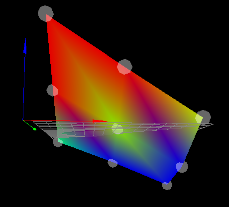
She knows the map and everything, but the right side is tight and the left side is loose, funny that the front and back are fine, it looks like the x is inverted,
but only on the height map, because the piece is coming out right
-
@3dcloner said in Offset on height map:
@fcwilt I don't use the assistant, in fact I found out about it today doing the research... Do you think it can solve it?
I use the bed leveling assistant to get the bed as level as possible.
Then I rely on the mesh bed compensation feature to deal with bed irregularities.
After using the bed leveling assistant you can create a 4 point height map just to verify that the bed is level to your satisfaction.
Then you can create the actual height map using a suitable number of points.
Frederick
-
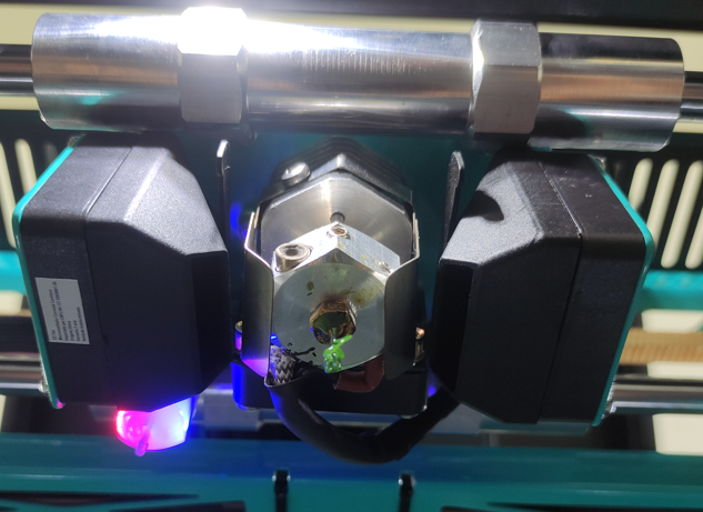
Can you share a photo of the print head showing the probe mounting position?
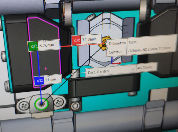
Are your probe XY offsets correct?
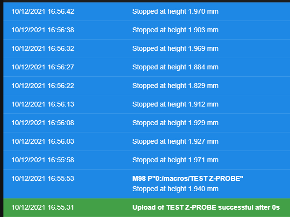
If you do a G30 S-1 test at multiple points on the bed do they stay consistent or do they change with XY position?
-
@fcwilt I used the assistant, but the problem persists, it seems that it has a tendency for the right side to be tight and the left side loose, both with the table level, with it not level, with the right side higher or the left higher, whatever, always the same result.
-
@fcwilt For sure!


In relation to the value it is correct, but it may be that I have inverted the meaning. But I've been trying a lot of things all day, and inverting the Z-Probe offsets was one of them.
In relation to the G30 S-1. I made a macro with some dots, follow the code.
G28

G1 X35 Y100 Z15
G30 S-1
G1 X85 Y100 Z15
G30 S-1
G1 X170 Y100 Z15
G30 S-1
G1 X255 Y100 Z15
G30 S-1
G1 X320 Y100 Z15
G30 S-1

G1 X35 Y200 Z15
G30 S-1
G1 X85 Y200 Z15
G30 S-1
G1 X170 Y200 Z15
G30 S-1
G1 X255 Y200 Z15
G30 S-1
G1 X320 Y200 Z15
G30 S-1
this was the result (the height map was loaded)

-
@phaedrux When I see the symptoms, it seems that the spindle pitch is wrong when it comes to X compensation, because the Y axis is right and the Z steps per mm are right, I even saw it on the dial indicator. Besides the direction of rotation of the spindle is right, when it has to lower it it lowers, but not enough, the same thing when it needs to lower (on the X axis).
-
G31 P500 X-34.3 Y31 Z2.195
Based on your photo your G31 looks more or less correct.
Do you happen to have a M376 command anywhere in your startup gcode or elsewhere to configure some compensation taper?
-
@phaedrux Good morning, getting back to work! Good week to you!
About the G31 I even tried another configuration, as can be seen in config.g, but nothing changed.
About the M376, I don't use it, why? -
@phaedrux I'm taking a look at the Gcode G30 and its H parameter, it could be a solution, but I don't quite understand how I use it, could you help me?
-
@3dcloner said in Offset on height map:
M558 P9 C"^zprobe.in" H4 F240 T19800
I don't think G30 H is the solution. It seems as though your trigger heights are not consistent. I suggest modifying your M558 to try and improve it.
Try this line
M558 P9 C"^zprobe.in" H3 F60 T12000 A10 R0.2 S0.003 B0In your homeall you can speed up the homing process by using a faster speed for the first homing and then slow down for a repeat. like this
M558 F240 A1
G30
M558 F60 A10
G30 -
@phaedrux said in Offset on height map:
In your homeall you can speed up the homing process by using a faster speed for the first homing and then slow down for a repeat. like this
M558 F240 A1
G30
M558 F60 A10
G30Why that approach instead of Faaa:bbb?
Thanks.
Frederick
-
@fcwilt Habit.
-
@phaedrux @fcwilt Got it, I can adopt this homing with two speeds, it might be useful since the machine is quite big, etc.
But I have good news, our team has been working here since Friday trying to find the problem and we did it. The y-axis rods were slightly bent, which made the X-axis twist,
which consequently changed the distance between the nozzle and the Z-Probe along the X axis. Before, we had no problems with this slight misalignment because we didn't use a Z-Probe, and that's why it took us a while to check this alignment.Finally, thank you very much for your help and attention, I learned several new things in the process. Case closed.
-
 undefined Phaedrux marked this topic as a question
-
 undefined Phaedrux has marked this topic as solved