mesh compensation - effect on G30 command
-
Working on a new home-built printer and having some issues with first layer and I have a question about my plans to confirm the mesh is working properly.
After homing (G28), leveling (G30, 3 points), re-homing (G28 Z), and running the mesh (G29 S0), I want to move the z probe to some of the positions I set up in the mesh and probe them with a G30 S-1.
My question for the forum is whether the result I get will be "compensated" (and therefore very close to 0), or "raw" (and therefore close to the heightmap.csv value at that point?
I want to use this knowledge to assure myself that the mesh probing worked and that compensation is active.
The behavior of my printer is that printing at the center of the bed is good, but the first layers out towards the corners are bad - mostly seems the nozzle is too close to the bed.
It's early days for this printer, nozzle, extruder setup, so it could be some other issue - I just want to be able to check mesh compensation issues off my list.
Thanks for any help.
-
Best best is to sahe your actual gcode files being used for homing and leveling so we can see what is happening.
The best way to verify if the mesh is working correctly is to use a bed leveling test print and print it twice. Once without mesh active, and once with it active.
-
I don't think it's the gcode, but as I used to say before retiring.. "pilot error is the easiest thing to fix". I'm only including what I believe are the relevant snippets of my files because I have lots of comments making the files pretty long. If the complete files seem necessary, I can post those.
From config.g, in the order they appear.
I use a global variable to capture offsets for my touch Z probe
set global.Z_probe_Xoffset = -37.5 Create variable global.Z_probe_Xoffset and set it's value. set global.Z_probe_Yoffset = 57;!- Create variable global.Z_probe_Yoffset and set it's value. Setting X Y and Z limits
M208 X-2:350 ;!Set the Min:Max X axis soft limits. Min position is value set when X endstop is triggered. M208 Y-10:350 ;!Set the Min:Max Y axis soft limits. Min position is value set when Y endstop is triggered. M208 Z-4:410 ;!Set the Min:Max Z axis soft limits. Max position is value set when Y endstop is triggered if using the endstop at the bottom of the travel. Set kinematics
M669 K1 ; CoreXY modeDefine Z probe
M558 P9 C"^zprobe.in" H3 A1 T10000 F600:30 S0.02 ;!Probe definition: ;!- P4 = probe type is a switch connected to something other than the z-endstop switch. ;!- ^C4 = connected to E1 endstop connector. the "^" character enables the pullup resistor ;!- H3 = using dive height (fast move to this z) 3mm ;!- A1 = on probe request, probe the location 1 time ;!- T = the a travel speed between points is 10000mm.min (T10000) ;!- F = using a dual probe speed Zmovement) 600mm/min to get close, then 30mm/min for accuracy ;!- s = with a tolerance of 0.02mm for multiple probes (probes out of tolerance will be repeated). M950 S0 C"duex.pwm5" ;! Define probe deployment pine for the BLTouch probe. ;! S0 = define this connector as Servo #0 ;! C"!duex.pwm5" = create this servo 0 on pwm5 pin on DuEx board. Aliases for this pin are: exp.heater7, exp.31, !duex.e6heat, !duex.pwm5 Set bed mesh parameters
M557 X0:{345 + global.Z_probe_Xoffset} Y{5+global.Z_probe_Yoffset}:345 P5 ;!- Define bed compensation probing grid. Min and max X and Y box edges for probing, P5 defines 5 points in each direction (a 5 x 5 probe matrix). Set locations of bed kinematic supports
M671 X-28.517:378.517:175 Y27.5:72.5:431.313 S10 ; Front Left: (-28.517, 72.5) | Front Right: (378.517, 72.5) | Back: (175, 413.313)That's everything in config.g
My sequence for use is Home Z (which homes X and Y also).
Home Z:
G91 ; Set relative positioning G1 H2 Z10 F1000 ; lower Z relative to current position in case the bed is in a position wehre the probe is currently triggered. G90 ; Return to absolute positioning. ;################ ;!If X has not been homed, home x if !move.axes[0].homed M291 P"X axis not yet homed. Homing now." R"Z-home using probe" S0 T5 ; S0 means no buttons, t5 means wait 5 seconds and move on. M98 P"0:/sys/homex.g" ; run the homex gcode file in the sys directory. Note line leading spaces needed to define IF Block 0:/sys/homex.g is the way to write an absolute path ;else ;M291 p"X already homed, moving on." s0 ;################;! If Y has not been homed, home Y if !move.axes[1].homed M291 P"Y axis not yet homed. Homing now." R"Z-home using probe" S0 T5 ; S0 means no buttons, t5 means wait 5 seconds and move on. M98 P"0:/sys/homey.g" ; run the homey gcode file in the sys directory. Note line leading spaces needed to define IF Block 0:/sys/homey.g is the way to write an absolute path ;else ;M291 p"Y already homed, moving on." s0 ;################;! Move the probe to the center of the bed quickly. G1 X{175 + global.Z_probe_Xoffset} Y{175+global.Z_probe_Yoffset} F6000 ;################;! Probe the bed and set the probe trigger point to Z=0 G30 I level and create the mesh for each print (adds time, but useful for my maker space where people might be inexperienced or swapping print beds of varying thickness or quality). As a result, bed leveling and the call for bed.g are in start.g.
start.g
;HOMING AND BED LEVEING G28 ; home all axes G32 ; run bed.g macro, which levels the bed (unless we add more to it) G29 S0; execute bed mesh measurement ;READY TO PRINT G1 Z15 F5000 ; lift the nozzle (move the bed down) 15mm so the move to the first printing point will be above the bed. A little while back, we discovered that we were running G29 without S0, but we are still having issues after fixing that.
Here's bed.g
M561 ;! clear any existing bed transform. ;! ;! probe three points on the bed to gather z-probe heights and on the last probe, add the S3 command that tells the Duet2 FW to perform 3 z-motor leveling. This also relies on an M671 code in the config.g file that defines the locations of the kinematic balls. Maybe that command belongs in this file. I don;t think there are other files that make independent z-motor moves and which would need it. G30 P0 X{175+global.Z_probe_Xoffset} Y{345 + global.Z_probe_Yoffset} Z-99999 ; Probe near back lead screw. global variables set in config.g file G30 P1 X00 Y{110.6+global.Z_probe_Yoffset} Z-99999 ; Probe near front left lead screw. global variables set in config.g file G30 P2 X{321.5 + global.Z_probe_Xoffset} Y{110.6+global.Z_probe_Yoffset} Z-99999 S3 ; Probe near front right lead screw and calibrate 3 motors. global variables set in config.g file M98 P"homez.g" ;Rehome the Z because leveling the bed surely moved the vertical location of the center of the bed. G1 g0 X{165 + global.Z_probe_Xoffset} Y{200+global.Z_probe_Yoffset} F10000 My sliced gcode files do not include any lines that would cancel or redo any of the bed mesh or leveling. And during execution, all the steps I call out are performed as expected.
Regarding the bed leveling test print idea, my latest brainwave is to write a macro that probes the bed at multiple locations and write the height results into the log. I could do this with mesh active and inactive to compare results. This seems to me to be more quantitative than looking at two prints (and avoids having the nozzle crash into the bed at some locations). Is there a reason this would not work?
And thanks for the stl file.
-
Hi,
Just FYI, rather than use variables to hold the z probe offsets you can get them directly from the object model.
This holds the X offset for probe 0:
sensors.probes[0].offsets[0]
This holds the Y offset for probe 0:
sensors.probes[0].offsets[1]
Frederick
-
Just FYI, when using the G30 P# syntax the XY position specified is the position that is probed. You don't need to make any adjustment for the probe offsets.
Frederick
-
@mikeabuilder said in mesh compensation - effect on G30 command:
Regarding the bed leveling test print idea, my latest brainwave is to write a macro that probes the bed at multiple locations and write the height results into the log. I could do this with mesh active and inactive to compare results. This seems to me to be more quantitative than looking at two prints (and avoids having the nozzle crash into the bed at some locations). Is there a reason this would not work?
Is your premise that having mesh compensation active during a G30 will affect the Z height results of G30? I don't think that's case. Though it is recommended to clear the heightmap or any compensation before going through your homing/leveling/meshing routine.
-
@fcwilt, thanks for the tips. Is there a downside to using the global variables as we are doing? I think our form makes the code more readable. But being a non-pro coder I've always opted for long variable names so I don't need to remember things like index 0 is X and index 1 is Y. But that's just me.
On the G30 comment, when we did not include the explicit probe offsets in the equation, our machine did not make those adjustments itself. To get the probe to the location we what to probe, we've had to include the probe offsets ourselves.
@Phaedrux, my goal with the macro is to use my touch probe to validate that the bed compensation is enabled. My original question on this post was to try to understand how the enabling or disabling of compensation affects the result reported by a G30. Rereading the the wiki more carefully:
G30 S-1 ; Probe the bed at the current XY position. When the probe is triggered, do not adjust the Z coordinate, just report the machine height at which the probe was triggered.
I think you're confirming that machine height is not affected by the compensation.
Is there any command that will report the active height compensation given X and Y locations as inputs (or maybe the current X and Y location)? If not, I guess I'm back to your earlier suggestion of a test print. Or maybe rigging up a dial gauge on my tool mount.
-
@mikeabuilder said in mesh compensation - effect on G30 command:
Is there any command that will report the active height compensation given X and Y locations as inputs (or maybe the current X and Y location)? If not, I guess I'm back to your earlier suggestion of a test print. Or maybe rigging up a dial gauge on my tool mount.
There might be something in the object model, but I'm not certain. You could also look at the heightmap display in DWC and hover over the various probe points to see the offset. The same can be viewed in the raw heightmap.csv. Or maybe I'm misunderstanding what you're looking for.
Regardless, a quick test print is a good way to see if the active compensation is having the correct effect since that's what matters most. If it doesn't have the right effect, the usual cause is probe offset being incorrect, mesh being too sparse to capture variance between points, or tilt of the print head causing the probe readings to vary with XY position.
-
@mikeabuilder said in mesh compensation - effect on G30 command:
@fcwilt, thanks for the tips. Is there a downside to using the global variables as we are doing? I think our form makes the code more readable. But being a non-pro coder I've always opted for long variable names so I don't need to remember things like index 0 is X and index 1 is Y. But that's just me.
Well then perhaps set the variable from the values in the object model so if you change the probe settings the variables will always be correct after reboot.
On the G30 comment, when we did not include the explicit probe offsets in the equation, our machine did not make those adjustments itself. To get the probe to the location we what to probe, we've had to include the probe offsets ourselves.
I double checked and the X and Y values are where the probe goes. Of course you have to be sure the values you specify can be reached by the probe.
Frederick
-
@fcwilt - Thanks for looking into the source code. I'll double check my observations (unfortunately not until next Tuesday). If I'm not getting the corrected location on a G30 XY, that might imply something else boogered up in my config somewhere. I might also attempt to edit the wiki for G30. It would be helpful (for me, anyway) to be explicit that the X and Y locations are with probe offsets included.
To quote Home Simpson, "DOH!" I have ho G31 in my config.g - That explains the lack of offsets being applied and me doing it manually - there are none!. Well, that's one problem down.
One more follow-on question on G30. Is G30 S-1 X Y Z-99999 a valid command without a P parameter? in the wiki, the Z-99999 reports a height error (which I think means the difference between the mesh corrected height and the machine height at point X Y), but is only described when using a P parameter. If it is valid, then it's a way for me to write the macro I seem so intent on writing.
-
@Phaedrux - I think you've hit on the root cause with your print head tilt comment. Looking at the relative locations of the probe and nozzle, if we have tilt, I can see where the height map would be affected. (see picture).
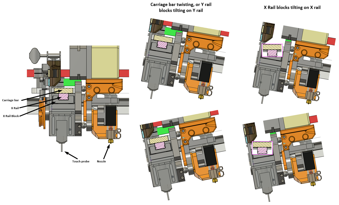
With a height map from a tilting print head, the mesh correction during printing for the same tilt would cause nozzle to crash or fly over the bed on the first layer, depending on the direction of tilt. Our height map data is consistent with this theory, and so is the nozzle crash and flight that we observed. The wiring to the print head is giving us the push or pull force to give the right torques to match this tilt, even though the forces are small. Something must be loose. So much alignment in the data makes me confident we are on the right track. Next will be to unravel what is loose or twisting. My current bet is on the sliding block the print head lives on. How to address it will be a "fun engineering problem".
Thanks to the forum for taking time to comment on this post. As always, the duet forum rocks! Too bad there is not a "best online forum" award.
-
undefined mikeabuilder referenced this topic 1 Jan 2022, 16:23