Utilizing Prusa Mini Fans with Duet 2 Wifi
-
@jrcl I don't have a Prusa but as far as I can remember the Prusa mini has 5v fans. Have you connected them to 5v ?
MIght be a stupid question but I have blown an expensive Noctua when I wasn't thinking ...
Voron V2.4 (#1317) with Duet 3 Mini5+ Wifi and 1LC v1.1 Toolboard
Voron V0.1 (#637) with Duet 3 Mini 5+ Wifi and 1LC v1.2 Toolboard
Ender 3 Pro with BTT SKR-2 + RRF -
@jrcl said in Utilizing Prusa Mini Fans with Duet 2 Wifi:
Both fans are 3 wire fans.
Three wire are generally +/- power plus tacho out.
It's four wire ones that have a separate PWM input.It is possible that connecting power to the tacho wire has damaged them.
Robert J.
Printers: Overlord pro, Kossel XL+ with Duet 6HC and "Frankentron", TronXY X5SA Pro converted to E3D toolchange with Duet 6HC and 1LC toolboards.
-
@gixxerfast Like connected them to the 3 header pins below the FAN0 pins?
-
@rjenkinsgb I figured there might be a chance of that. I guess I better buy some extra 2 wires fans just to make my life easier and wait for them to arrive. Darn you impatience!
-
-
@gixxerfast No I had been attempting to use this as a guide and only use the 2 wire FAN0 pinout with 2 of my 3 wires from the fan. I have not used the 3 header pins with your arrow
https://duet3d.dozuki.com/Wiki/Connecting_and_configuring_fans
-
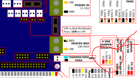
@jrcl OK, those three pins are used to select the V_FAN voltage that is used where you connected your fans. You can choose between Vin (24V ?) or 5v by setting a jumper over the rightmost pins or the left most. I guess you have such a jumper (bridge) already in place there, otherwise I guess you have no fan power at all.
Voron V2.4 (#1317) with Duet 3 Mini5+ Wifi and 1LC v1.1 Toolboard
Voron V0.1 (#637) with Duet 3 Mini 5+ Wifi and 1LC v1.2 Toolboard
Ender 3 Pro with BTT SKR-2 + RRF -
This post is deleted! -
@gixxerfast Yes, there appears to be some sort of cover between the 2 far-right pins which is serving as the jumper I'm guessing? Should I use a multimeter across the FAN0 position to see if it's outputting a voltage signal?
-
@jrcl Just be very very very careful not to short anything as it's really easy to do when probing like 2 pin connectors. I'm sort of clumpsy that way so I always use jumper wires when probing.
If yu had the jumper on the far right pins (assuming we have the same reference) you have fed your fans Vin which I (again) guess is 24V. That usually doesn't end well for the fans.
-
@gixxerfast Yeahhhhh..... Now that you say that I do not trust myself to possibly bump another pin. Okay so that's not an option. It's clearly set for 5V and after researching Prusa fans, mine should be too. I mean if I put a 5V external power supply to the red and black wires on it, it powers on. However when I put those pins onto the Duet, no dice
-
@jrcl Can you post a picture of that area of your board showing the jumpers and how you connect the fans? You can leave the board unconnected (unpowered).
-
hopefully this is what you were looking for
-
@jrcl Yes thank you.
It shows clearly that you are feeding your fans Vin. That is the voltage that you are feeding into the board and since 12 is not common today I assume that that is 24V. I cannot understand how they would survive that. You are powering your board via a power supply and not via the USB, right?You should move that jumper to the far left side.
Also, I forgot these are not JST XH connectors so they are pretty easy to probe. Just probe on the left pin on your fan connector and the black probe on the SD card metal thingy.
That won't tell you much though since the control of the fan is done via the ground (V-) pin.
Start with moving the jumper. Black plastic thing on the three pin header to the left.
-
@jrcl After you have moved the jumper to select 5v fan voltage and just want to test your fans, move the fan connector to the right-most always on fan terminal. Then it will start without any fan configuration.
-
@gixxerfast Great idea! I tried that and got the part cooling/nozzle fan working on the ALWAYS ON FANS but once back on the FAN0 I got no response utilizing the DWC fan control slider.
The heat sink fan worked for neither. I think I may have fried that one earlier with my misc troubleshooting. It has a blue tacho wire though so I'm not sure if I can test it with a multimeter or power supply separate from the duet.
-
@jrcl Yeah the 5v fan that survives 24V must be something else. My €30 Noctua didn't/wasn't
Maybe you can show the config.g? Use the </> formatting so it's easy to read. It's like a mess otherwise.
-
@gixxerfast yeah, I think you are right. My sources weren't great anyhow so certainly wouldn't be surprised. Here is my config.g
; Configuration file for Duet WiFi (firmware version 3.3) ; executed by the firmware on start-up ; ; generated by RepRapFirmware Configuration Tool v3.3.10 on Thu Dec 16 2021 23:41:39 GMT-0500 (Eastern Standard Time) ; General preferences M575 P1 B57600 S1 ; Paneldue Update??? G90 ; send absolute coordinates... M83 ; ...but relative extruder moves M550 P"CIS_MK2" ; set printer name ; Network M552 S1 ; enable network M586 P0 S1 ; enable HTTP M586 P1 S0 ; disable FTP M586 P2 S0 ; disable Telnet ; Drives M569 P0 S1 ; physical drive 0 goes forwards M569 P1 S1 ; physical drive 1 goes forwards M569 P2 S1 ; physical drive 2 goes forwards M569 P3 S1 ; physical drive 3 goes forwards M584 X0 Y1 Z2 E3 ; set drive mapping M350 X16 Y16 Z16 E16 I1 ; configure microstepping with interpolation M92 X80.00 Y80.00 Z400.00 E420.00 ; set steps per mm M566 X900.00 Y900.00 Z60.00 E120.00 ; set maximum instantaneous speed changes (mm/min) M203 X6000.00 Y6000.00 Z180.00 E1200.00 ; set maximum speeds (mm/min) M201 X500.00 Y500.00 Z20.00 E250.00 ; set accelerations (mm/s^2) M906 X800 Y800 Z800 E800 I30 ; set motor currents (mA) and motor idle factor in per cent M84 S30 ; Set idle timeout ; Axis Limits M208 X0 Y0 Z0 S1 ; set axis minima M208 X152 Y152 Z152 S0 ; set axis maxima ; Endstops M574 X1 S3 ; configure sensorless endstop for low end on X M574 Y1 S3 ; configure sensorless endstop for low end on Y M574 Z1 S3 ; configure sensorless endstop for low end on Z M915 X Y R0 F0 ; Last main command needed for sensorless homing ; Z-Probe M558 P0 H5 F120 T6000 ; disable Z probe but set dive height, probe speed and travel speed M557 X15:137 Y15:137 S20 ; define mesh grid ; Heaters M308 S0 P"bedtemp" Y"thermistor" T100000 B4138 ; configure sensor 0 as thermistor on pin bedtemp M950 H0 C"bedheat" T0 ; create bed heater output on bedheat and map it to sensor 0 M307 H0 B1 S1.00 ; enable bang-bang mode for the bed heater and set PWM limit M140 H0 ; map heated bed to heater 0 M143 H0 S120 ; set temperature limit for heater 0 to 120C M308 S1 P"e0temp" Y"thermistor" T100000 B4138 ; configure sensor 1 as thermistor on pin e0temp M950 H1 C"e0heat" T1 ; create nozzle heater output on e0heat and map it to sensor 1 M307 H1 B0 S1.00 ; disable bang-bang mode for heater and set PWM limit M143 H1 S280 ; set temperature limit for heater 1 to 280C ; Fans M950 F0 C"fan0" Q500 ; create fan 0 on pin fan0 and set its frequency M106 P0 S0 H-1 ; set fan 0 value. Thermostatic control is turned off M950 F1 C"fan1" Q500 ; create fan 1 on pin fan1 and set its frequency M106 P1 S1 H1 T45 ; set fan 1 value. Thermostatic control is turned on ; Tools M563 P0 D0 H1 F0 ; define tool 0 G10 P0 X0 Y0 Z0 ; set tool 0 axis offsets G10 P0 R0 S0 ; set initial tool 0 active and standby temperatures to 0C ; Custom settings are not defined -
@jrcl Thanks! Well it look good as far as I can tell. I can only think of moving it to fan2 and alter the config accordingly and try. Otherwise creo que es muerto in some way
-
@gixxerfast I'll make sure to give that a run too. Either way thanks for showing me some good ways to troubleshoot fan problems!