Dashboard Fan Object
-
I'm trying to control two "fans" for use as part cooling on my 3HC expansion board using the "1.out3" and 1.out4" pins with 1 being the address of my board. I have the tools named "L Tool Air" and "R tool Air." It appears that in DWC, fan0 is automatically named "Tool Fan" under the dashboard "Fan Control" section. however, If I name F0 with
C"L Tool Air"in setup, the Dashboard will list both Tool Fan and L Tool Air, with both controlling the same fan output. Is there a way to get rid of the automatic "Tool Fan" object in the dashboard so I only have my L Tool Air and Right Tool Air? I'm assuming the Hotend Fans don't show up, since they are thermostatically controlled?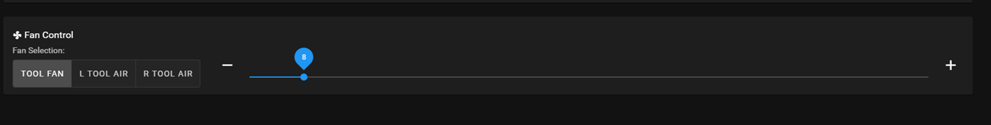
; General preferences G90 ; send absolute coordinates... M83 ; ...but relative extruder moves M550 P"Duet 3" ; set printer name M150 X0 ; set LED type to DotStar M150 R0 U0 B0 P0 S71 ; clear all LEDs G4 S5 ; allow time for 3HC to boot ; ***** Drives ***** ; 6HC Main Board M569 P0.0 S0 ; physical drive 0.0 goes reverse - Right Y Axis M569 P0.1 S0 ; physical drive 0.1 goes reverse - X Axis Hotend M569 P0.2 S1 ; physical drive 0.2 goes forwards - Left Y Axis M569 P0.3 S1 ; physical drive 0.3 goes forwards - Left Extruder M569 P0.4 S0 ; physical drive 0.4 goes reverse - U Axis Hotend M569 P0.5 S1 ; physical drive 0.5 goes forwards - Right Extruder M150 R255 U0 B0 P128 S5 F1 ; set 5 LEDs to red ; 3HC Expansion Board M569 P1.0 S1 ; physical drive 1.0 goes forwards - Z Axis Front-Left M569 P1.1 S1 ; physical drive 1.1 goes forwards - Z Axis Back-Center M569 P1.2 S1 ; physical drive 1.2 goes forwards - Z Axis Front-Right M150 R255 U0 B0 P128 S5 F1 ; set 5 LEDs to red ; set stepper parameters M584 X0.1 Y0.0:0.2 Z1.0:1.1:1.2 U0.4 E0.3:0.5 ; set drive mapping M350 X16 Y16 Z16 U16 E16:16 I1 ; configure microstepping with interpolation M92 X40.00 Y80.00 Z1600.00 U40.00 E400.00 ; set steps per mm M566 X900.00 Y900.00 Z60.00 U900.00 E120.00 ; set maximum instantaneous speed changes (mm/min) M203 X12000.00 Y12000.00 Z1000.00 U12000.00 E1800.00 ; set maximum speeds (mm/min) M201 X500.00 Y500.00 Z20.00 U500.00 E250.00 ; set accelerations (mm/s^2) M906 X1500 Y1500 Z1500 U1500 E300 I30 ; set motor currents (mA) and motor idle factor in per cent M84 S30 ; Set idle timeout M150 R255 U0 B0 P128 S5 F1 ; set 5 LEDs to red ; Axis Limits M208 X0 Y0 Z0 U45 S1 ; set axis minima M208 X370 Y400 Z380 U411 S0 ; set axis maxima M150 R255 U0 B0 P128 S2 F1 ; set 2 LEDs to red ; Z leadscrew locations M671 X-54:206:466 Y-39.5:428:-39.5 S10 ; three leadscrews at Front-Left, Back-Center, and Front-Right M150 R255 U0 B0 P128 S2 F1 ; set 2 LEDs to red ; Endstops M574 X1 S1 P"io0.in" ; configure active-high endstop for low end on X via pin io0.in M574 Y2 S1 P"io2.in+io1.in" ; configure active-high endstop for high end on Y via pin io1.in M574 U2 S1 P"io3.in" ; configure active-high endstop for high end on U via pin io1.in M150 R255 U0 B0 P128 S5 F1 ; set 5 LEDs to red ; Z-Probe M950 S0 C"1.io1.out" M558 P9 C"1.io1.in" F200 H5 R0 T6000 A S0.03 B1 ; set Z probe type to switch and the dive height + speed G31 X-5 Y21.75 Z3.8 ; set Z probe offset and trigger height M557 X0:350 Y22:400 S50 ; define mesh grid M150 R255 U0 B0 P128 S5 F1 ; set 5 LEDs to red ; ***** Heaters ***** ; Bed M308 S0 P"temp0" Y"thermistor" A"Bed Temp" T100000 B3950 ; configure sensor 0 as thermistor on pin temp0 M950 H0 C"out0" T0 ; create bed heater output on out0 and map it to sensor 0 M307 H0 R0.601 C403.2 D5.29 S1.00 ; disable bang-bang mode for the bed heater and set PWM limit M140 H0 ; map heated bed to heater 0 M143 H0 S120 ; set temperature limit for heater 0 to 120C M150 R255 U0 B0 P128 S5 F1 ; set 5 LEDs to red ; Left Hotend (X) M308 S1 P"temp1" Y"thermistor" A"Left Temp" T100000 B4725 C7.06e-8 ; configure sensor 1 as thermistor on pin temp1 M950 H1 C"out1" T1 ; create nozzle heater output on out1 and map it to sensor 1 M307 H1 R2.392 C206.4 D5.67 S1.00 V24.0 ; disable bang-bang mode for heater and set PWM limit M143 H1 S280 ; set temperature limit for heater 1 to 280C M150 R255 U0 B0 P128 S5 F1 ; set 5 LEDs to red ; Right Hotend (U) M308 S2 P"temp2" Y"thermistor" A"Right Temp" T100000 B4725 C7.06e-8 ; configure sensor 2 as thermistor on pin temp2 M950 H2 C"out2" T2 ; create nozzle heater output on out2 and map it to sensor 2 M307 H2 R2.132 C230.6 D5.30 S1.00 V24.0 ; disable bang-bang mode for heater and set PWM limit M143 H2 S280 ; set temperature limit for heater 2 to 280C M150 R255 U0 B0 P128 S5 F1 ; set 5 LEDs to red ; ***** Fans ***** ; Left Tool Air (X) M950 F0 C"1.out3" Q50 ; create fan 0 on pin 1.out3 and set its frequency M106 P0 C"L Tool Air" ; ; Left Heater Fan (X) M950 F1 C"out7" Q250 ; create fan 1 on pin out7 and set its frequency M106 P1 S1 H1 T45 C"L Hotend Fan" ; set fan 1 value. Thermostatic control is turned on M150 R255 U0 B0 P128 S5 F1 ; set 5 LEDs to red ; Right Tool Air (U) M950 F2 C"1.out4" Q50 ; create fan 2 on pin 1.out4 and set its frequency M106 P2 C"R Tool Air" ; Right Heater Fan (U) M950 F3 C"out8" Q250 ; create fan 3 on pin out8 and set its frequency M106 P3 S1 H2 T45 C"R Hotend Fan" ; set fan 3 value. Thermostatic control is turned on M150 R255 U0 B0 P128 S5 F1 ; set 5 LEDs to red ; ***** Tools ***** ; Left Tool (X) M563 P0 S"Left" D0 H1 F0 ; define tool 0 G10 P0 X0 Y0 Z0 ; set tool 0 axis offsets G10 P0 R0 S0 ; set initial tool 0 active and standby temperatures to 0C M150 R255 U0 B0 P128 S5 F1 ; set 5 LEDs to red ; Right Tool (U) M563 P1 S"Right" D1 H2 X3 F1 ; define tool 1 G10 P1 X45 Y0 Z0 ; set tool 1 axis offsets G10 P1 R0 S0 ; set initial tool 1 active and standby temperatures to 0C M150 R255 U0 B0 P128 S5 F1 ; set 5 LEDs to red ; Dual Tools M563 P2 S"Dual" D0:1 H1:2 X0:3 F0:1 G10 P2 X100 Y0 U-100 S0 R0 M567 P2 E1:1 M150 R255 U0 B0 P128 S5 ; set 5 LEDs to red ; Miscellaneous T0 ; select first tool M150 R128 U36 B0 P128 S71 ; set all LEDs to amber -
@vbuys The tool fan is the fan mapped to the currently selected tool. It is the one that is controlled by the slicer (i.e. M106 without P parameter). You can change the assignment via the M563 F parameter or yo can remove it altogether by specifying F-1 although you may need a recent beta for this.
-
@vbuys As @chrishamm has said, the tool fan is the currently selected tool so does give duplication which in some instances can seem unnecessary. However, looking at your configuration, you might find it better to keep it. The reason being that when you have selected P2 (both tools), the Tool Fan of DWC will control them both together, whereas selecting one of the other buttons will only control each fan individually.
-
@deckingman @chrishamm Thanks for the replies! That clarifies things for me on how DWC operates. and it does make sense to keep it in light of @deckingman comments
@deckingman said in Dashboard Fan Object:
when you have selected P2 (both tools), the Tool Fan of DWC will control them both together, whereas selecting one of the other buttons will only control each fan individually.