1LC v1.1 toolboard 5v control
-
Hello to all,
We need to be able to control a 5v DC micro motor vibrator from the 1LC board (v1.1).
We already have the following pins occupied:
Io1: io1.in, gnd - tool detector bit1.
Out2: out2, +vout -UV curing leds
Out0: both pins -solenoid with antiparallel diode
Temp0: both pins -thermistor
Io2: io2.in, gnd - tool detector bit2
Io0: io0.in, gnd - endstopSo we only have Out1 but we don't have 5v rail there. We have 12v as the jumper selected. If possible we would like to avoid install an aditional buckdown.
Is there any way to control a 5v output with the available free pins?
-
@marcossf how much current does the motor draw; and will it be run continuously or intermittently? You may be able to run it from OUT1 using one of the following schemes:
(1) Connect a 6.8V Zener diode in series with it. If the motor draws 100mA then it will dissipate about 0.7W of power, so a 1W Zener diode would do.
(2) Connect it to OUT1 via a L-C smoothing network and run it at about 40% 65kHz PWM. This is more efficient, but carries the risk that you might accidentally drive it at full PWM, i.e. 12V.I don't advice powering it from the internal 5V supply, because that supply is derived from 12V using a linear regulator, so the regulator would get hot.
Duet WiFi hardware designer and firmware engineer
Please do not ask me for Duet support via PM or email, use the forum
http://www.escher3d.com, https://miscsolutions.wordpress.com -
@dc42 It's a very tiny motor, similar to a brushless fan.
Rated voltage: 5.0 V, rated power: 0.2 W, rated current: 0.04 A, rated speed: 11500 rpm
It would be used in pulses, max 1-1.5 second long, but it needs to do it repetively. For example 1 second activation, and 5 seconds idle and so on.
It is used to prevent micro-grain material from compacting in a gravity chute.
The option 1 proposed is clear, but for option 2, I don't undestand how to do it.
-
@marcossf I expect you will configure the port that controls the motor as a GpOut port and then use M42 to turn it on/off. If you use the Zener diode, then you would use M42 P# S1 (where # is the GpIo port number you choose) to turn it on, and M42 P# S0 to turn it off. If you connect it directly then you would use M42 P# S0.4 to turn it on (S0.4 t give 40% PWM instead of S1).
The PWM approach may work without using a LC filter; but using the LC filter may prolong the life of the motor. I can provide more details o the LC filter if you need it.
HTH David
Duet WiFi hardware designer and firmware engineer
Please do not ask me for Duet support via PM or email, use the forum
http://www.escher3d.com, https://miscsolutions.wordpress.com -
@dc42 Thank you David.
Yes it will be controlled by M42 gcode. We are going to test the PWM approach proposed, as the client will not touch the configurations or parameters that we make in the code.
However, I would like to know more about the LC filter to have an additional security alternative. We already have some suspicions about the supposed durability of these micro motors, with the additional handicap of vibration, which is never a good thing.
-
@marcossf I suggest a 4.7mH inductor rated at 0.1A or higher between the OUT1_NEG pin and the negative motor terminal, and then a 10uF 25V capacitor connected in parallel with the motor. Don't use the capacitor without also using the inductor. Set the PWM frequency to 65000 in the M950 command.
Duet WiFi hardware designer and firmware engineer
Please do not ask me for Duet support via PM or email, use the forum
http://www.escher3d.com, https://miscsolutions.wordpress.com -
@dc42 OK, thank you.
I'll prototype a small PCB to fit these components inside printheads, and test it.
I guess with this board between the 1LC and the motor it means we can use M42 S1 and will send full 12V to Out1 without any problems. -
@marcossf said in 1LC v1.1 toolboard 5v control:
@dc42 OK, thank you.
I'll prototype a small PCB to fit these components inside printheads, and test it.
I guess with this board between the 1LC and the motor it means we can use M42 S1 and will send full 12V to Out1 without any problems.No, you would still need to use M42 S0.4.
OTOH if you use the 6.8V Zener diode in series with the motor instead, you can use M42 S1. As the motor running current is only 40mA, the Zener diodes will only dissipate about 270mW after starting, so it is a reasonable solution. I still suggest you use a 1W Zener diode, not a 400mW one, to better handle the starting current surge.
Duet WiFi hardware designer and firmware engineer
Please do not ask me for Duet support via PM or email, use the forum
http://www.escher3d.com, https://miscsolutions.wordpress.com -
@dc42 OK, so it looks more simple and safe enough use the diode solution then, isn't it?
-
@marcossf said in 1LC v1.1 toolboard 5v control:
@dc42 OK, so it looks more simple and safe enough use the diode solution then, isn't it?
Yes.
Duet WiFi hardware designer and firmware engineer
Please do not ask me for Duet support via PM or email, use the forum
http://www.escher3d.com, https://miscsolutions.wordpress.com -
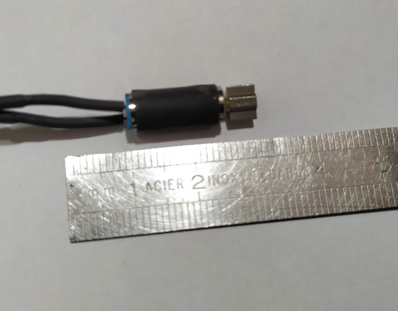
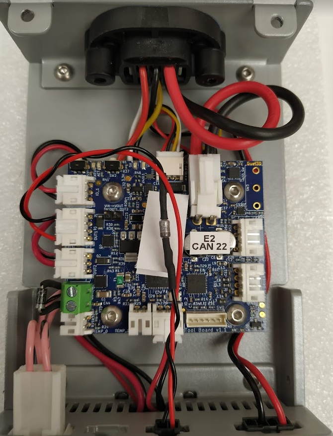
@dc42 OK, done. We are going to test it.
Just for double check, but I think all pins and diodes looks correct, isn't it.
-
@marcossf it looks to me that the connections to the OUT1 port are wrong. Black should go to the OUT1_NEG pin, and red to the VOUT pin.
Duet WiFi hardware designer and firmware engineer
Please do not ask me for Duet support via PM or email, use the forum
http://www.escher3d.com, https://miscsolutions.wordpress.com -
@dc42 OUT 1 block pins are marked like so in the schematics:
GND
+VOUT
out1.tach
out1Do you mean we need to connect +VOUT to the motor positive and out1 to the negative?
It's confuse to me.
-
@marcossf yes. All the outputs on duet boards switch to ground
-
@jay_s_uk OK, thanks Jay.