Wiring SuperPinda Z Probe & Microswitch XY Endstops Duet 3
-
I am wiring up my Duet 3 Mini 5+ and just want to double-check some information.
I have microswitch X and Y end stops. I've connected to the outside terminals NC ends of the switch, I assume these switches must connect to the 5V_EXT and ioN.in pin of one of the IO_N terminals.
As for the Z Probe, I have an inductive probe. It's got Brown, Blue and Black wires. It's a Super Pinda probe from Prusa and I believe this is the data sheet (it has the pepperl-fuchs on the label). On the datasheet there's this diagram:
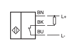
I guess that means BN = BrowN, BK = BlacK and BU is BlUe
Which pins do they go to? My guess would be Brown 5V, Black ioN.in and Blue GND
Has anyone else had success with this probe?
-
Microswitches are usually connected ground to io.in and as nc.
Read this https://duet3d.dozuki.com/Wiki/M574#Section_M574_RepRapFirmware_Num_3 for more info
Regarding the Superpinda, I have one on front of me now connected to my breadboard.
Yes, Brown is +5V and Blue is -V. Black is signal and output 5V when close to metal. You need a steel surface to trigger against. It will not react on aluminium.
-
Thanks.
I looked at the configurator and see there are many options:
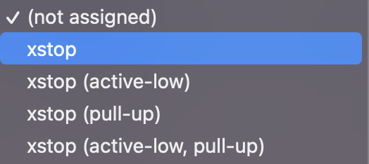
I guess you can do either unless I misunderstand what these options mean.
-
Aha! Reading this Ender 3 Pro Guide I now see why you'd want to do it that way.
I notice that IO5/6 only have 3 pins so the other inputs are more versatile.
I must admit, the docs are difficult to follow! This Ender 3 guide contradicts the wiring guide which says IO 0-4 are for endstops and mentions nothing on IO 5 & 6.
-
@daveh said in Wiring SuperPinda Z Probe & Microswitch XY Endstops Duet 3:
and mentions nothing on IO 5 & 6.
I'll add a note to io5 and 6 to explicitly say endstops. However, one of the main features of the Duet 3 is the versatile nature of the IO ports compared to having dedicated ports for specific hardware. The only differentiating thing between 5&6 and the rest is tha lack of PWM output, so literally perfect for simple endstops.