Duet3D Logo Duet3D
    • Tags
    • Documentation
    • Order
    • Register
    • Login

    Wiring

    Scheduled Pinned Locked Moved
    Duet Hardware and wiring
    2
    5
    231
    Loading More Posts
    • Oldest to Newest
    • Newest to Oldest
    • Most Votes
    Reply
    • Reply as topic
    Log in to reply
    This topic has been deleted. Only users with topic management privileges can see it.
    • Heideundefined
      Heide
      last edited by

      Hello

      I have a question in regards of the stepper motor wiring.

      On the drawing of the Duet3 board I can see that
      A2 = Black
      A1 = Green
      B2 = Blue
      B1 = Red

      But If I take a look at the MOONS MS17HD4P data sheet The colors of the wires are different from the Duet, and on the Hemere extruder another set of colors.

      Could I care less about the colors of the wires and just concentrate on the drawings?

      An example.
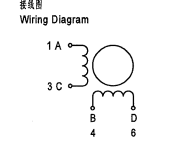
      A Moons stepper is catorised like this
      1A
      3C
      4B
      6D

      Would it then be
      Duet3 = Moons
      A2 = 1A
      A1 = 3C
      B2 = 4B
      B1 = 6D

      I am in doubt and I hope that you can help

      Voron CoreXY with Duet 3 + expansion + PanelDue 7i - 300 * 300 * 300 and Hemera Revo

      jay_s_ukundefined 1 Reply Last reply Reply Quote 0
      • jay_s_ukundefined
        jay_s_uk @Heide
        last edited by

        @heide said in Wiring:

        A2 = 1A
        A1 = 3C
        B2 = 4B
        B1 = 6D

        thats correct. see this bit of the datasheet
        f3f1485a-a97a-4de4-826b-66985c8fbab2-image.png
        1A and 3C are one pair and 4B and 6D are the other. On the duet boards, A1 and A2 are one pair and B1 and B2 are the other

        Owns various duet boards and is the main wiki maintainer for the Teamgloomy LPC/STM32 port of RRF. Assume I'm running whatever the latest beta/stable build is

        Heideundefined 1 Reply Last reply Reply Quote 0
        • Heideundefined
          Heide @jay_s_uk
          last edited by

          @jay_s_uk

          Thanks for the fast reply

          Okey, I will not be concerned about the colors then. To me they could all be black.
          I will treat them as pairs.

          Maybe you can answer one more question for me.

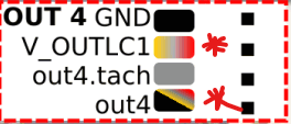
          Connecting the Fans to PWM OUT 4, 5 and 6.
          My fans are 2 pins. And in regards of the description I will have to connect them to

          V_OUT_LC_1 pin (+ve) and the OUT_n_NEG pin (-ve).

          But where is the OUT_n_NEG Pin. My thoughts is that it would be GND. Is this correct?

          Voron CoreXY with Duet 3 + expansion + PanelDue 7i - 300 * 300 * 300 and Hemera Revo

          jay_s_ukundefined 1 Reply Last reply Reply Quote 0
          • jay_s_ukundefined
            jay_s_uk @Heide
            last edited by

            @heide these ones 6cc39e7b-304d-446c-add0-28ed5418e2b2-image.png

            Owns various duet boards and is the main wiki maintainer for the Teamgloomy LPC/STM32 port of RRF. Assume I'm running whatever the latest beta/stable build is

            Heideundefined 1 Reply Last reply Reply Quote 0
            • Heideundefined
              Heide @jay_s_uk
              last edited by

              @jay_s_uk

              Then I have made it wrong. I am happy that it has not been powered on just yet. Thanks 🙂

              Voron CoreXY with Duet 3 + expansion + PanelDue 7i - 300 * 300 * 300 and Hemera Revo

              1 Reply Last reply Reply Quote 1
              • First post
                Last post
              Unless otherwise noted, all forum content is licensed under CC-BY-SA