MFM 0: tooLittleMovement
-
Here's config
; Configuration file for Duet WiFi (firmware version 2.03)
; executed by the firmware on start-up
;
; generated by RepRapFirmware Configuration Tool v3.2.2 on Mon Feb 08 2021 18:44:59 GMT-0500 (Eastern Standard Time); General preferences
G90 ; send absolute coordinates...
M83 ; ...but relative extruder moves
M550 P"My Printer" ; set printer name
M669 K1 ; select CoreXY mode; Network
M552 S1 ; enable network
M586 P0 S1 ; enable HTTP
M586 P1 S0 ; disable FTP
M586 P2 S0 ; disable Telnet; Drives
M569 P0 S0 ; physical drive 0 goes backwards
M569 P1 S0 ; physical drive 1 goes backwards
M569 P2 S1 ; physical drive 2 goes forwards
M569 P3 S0 ; physical drive 3 goes backwards
M584 X0 Y1 Z2 E3 ; set drive mapping
M350 Z16 I0 ; configure microstepping without interpolation
M350 X16 Y16 E16 I1 ; configure microstepping with interpolation
M92 X160.00 Y160.00 Z1600 E833.00 ; set steps per mm
M566 X850.00 Y850.00 Z80.00 E2000.00 ; set maximum instantaneous speed changes (mm/min)
M203 X9000.00 Y9000.00 Z900.00 E3800.00 ; set maximum speeds (mm/min)
M201 X1850.00 Y1850.00 Z120.00 E3800.00 ; set accelerations (mm/s^2)
M906 X1370 Y1370 Z1350 E1350 I30 ; set motor currents (mA) and motor idle factor in per cent
M84 S30 ; Set idle timeout; Axis Limits
M208 X0 Y0 Z0 S1 ; set axis minima
M208 X223 Y208 Z308 S0 ; set axis maxima; Endstops
M574 X1 S1 P"xstop" ; set active high endstops on low end of x travel
M574 Y2 S1 P"ystop" ; set active high endstop on high end of y travel
M574 Z1 S2 ; set endstops controlled by probe; Z-Probe
M307 H3 A-1 C-1 D-1 ; disable heater 3 on PWM channel for BLTouch
M950 H3 C"nil"
M950 S0 C"exp.heater3" ; create servo pin 0 for BLTouch
M558 P9 C"^zprobe.in" H8 F120 T6000 ; set Z probe type to bltouch and the dive height + speeds
G31 P25 X-33.33 Y-39.87 Z1.200 ; set Z probe trigger value, offset and trigger height
M557 X5:215 Y5:195 S20 ; define mesh grid;*** Thermistors
;* Bed
M308 S0 P"bedtemp" Y"thermistor" T100000 R4700 B4138
M950 H0 C"bedheat" Q10 T0
M307 H0 R0.379 C322.8 D1.81 S1.00 V24.1 B0 ; disable bang-bang mode for the bed heater and set PWM limit
;M305 P0 T100000 B4138 R4700 ; set thermistor + ADC parameters for heater 0
M140 H0 ;Map heater control to GUI
M143 H0 S110 ; set temperature limit for heater 0 to 110C;* Hotend
M308 S1 P"e0temp" Y"thermistor" T100000 R4700 B4725 C7.06e-8
M950 H1 C"e0heat" T1
M307 H1 R1.594 C336.7 D5.87 S1.00 V23.8 B0 ;disable bang-bang mode for the hotend and set PWM limit
;M305 P1 T100000 B4725 C7.06e-8 R4700 ; set thermistor + ADC parameters for heater 1
M143 H1 S280 ; set temperature limit for heater 1 to 280C; Fans
M950 F0 C"Fan0" Q500
M106 P0 S0 H-1 ; set fan 0 value, PWM signal inversion and frequency. Thermostatic control is turned offM950 F1 C"Fan1" Q500
M106 P1 S1 H1 T45 ; set fan 1 value, PWM signal inversion and frequency. Thermostatic control is turned onM950 F2 C"Fan2" Q500
M106 P2 S1 H1 T35 ; set fan 2 value, PWM signal inversion and frequency. Thermostatic control is turned onM950 F3 C"Fan" Q500
M106 P3 S1 H1 T45 ; set fan 3 value, PWM signal inversion and frequency. Thermostatic control is turned onM950 F4 C"Fan" Q500
M106 P4 S1 H1 T45 ; set fan 4 value, PWM signal inversion and frequency. Thermostatic control is turned onM950 F5 C"Fan" Q500
M106 P5 S1 H1 T45 ; set fan 5 value, PWM signal inversion and frequency. Thermostatic control is turned on; Tools
M563 P0 D0 H1 F0 ; define tool 0
G10 P0 X0 Y0 Z0 ; set tool 0 axis offsets
G10 P0 R0 S0 ; set initial tool 0 active and standby temperatures to 0C; Custom settings are not defined
; Miscellaneous
M575 P1 S1 B57600 ; enable support for PanelDue
M501 ; load saved parameters from non-volatile memory
M911 S10 R11 P"M913 X0 Y0 G91 M83 G1 Z3 E-5 F1000" ; set voltage thresholds and actions to run on power lossM591 D0 P3 C"e0_stop" S1 R50:140 L24.8 E5.0 A0 ; Duet3D rotating magnet sensor for extruder drive 0 is connected to E0
; endstop input,enabled, sensitivity 24.8mm.rev, 50% to 140% tolerance, 5mm
; detect length -
Anyone have any ideas? Is there something obvious I'm not seeing? Thanks to you all that have chimed in so far, I do appreciate the help.
-
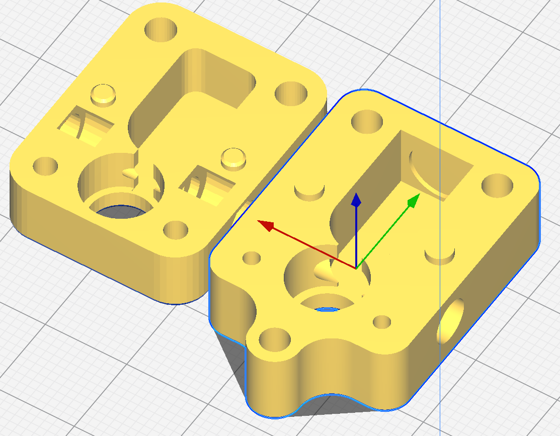
I'd guess at this being a mechanical issue. It certainly seems to have been with mine. I redesigned the case, re-printed and it's been perfect so far.
I've just posted my updated design over here in another thread if you're interested in trying it out. I don't have a resin printer, so put a bit of work into getting it tweaked for FDM. STL if you want 'em.
My recent thread here:
For what it's worth, 3.4RC2 cured the "sensor error" stops I was getting, but not the movement ones. The updated housing is going strong and the sensor has been flawless. Had a few "sensor error" drops from crimps that had lost some spring early on, but fresh ones did nothing to solve the "too little movement".
My current M591 D0
Duet3D rotating magnet filament monitor v3 on pin e0stop, enabled, sensitivity 26.67mm/rev, allow 70% to 130%, check printing moves every 6.0mm, version 3, mag 131 agc 69, measured sensitivity 26.57mm/rev, min 98% max 103% over 10401.0mm
That's on a print with 2800 x 6.5mm retracts!
-
@lo-fi
Thanks for your reply. I'm eager to see what you changed in the housing design that made the difference. I was thinking my problem may be the springs tension on the bearing starting to weaken as my sensor was working pretty well. I'm going to devote time to this over the weekend, I'll report back what I find. -
My design goals:
-
Keep the filament path clear of anything but the PTFE inserts, hob and idler.
-
Align the PTFE so the filament is lightly pressed against the hobb even before the idler comes into play
-
Add slightly more clearance for the hob and idler
-
Add an indent to keep the idler spring in the correct position
-
Achieve a tight fit for the plastic collets holding the PTFE
I used the official idler mounting, though I think I can tweak that a little too as the two halves required quite a bit of fettling to let the bearing spin freely but still hold it securely when glued together around it.
I think the key things that made the difference are keeping the filament path clear, stable and moving the hobb even without the idler. I don't think the idler spring is strong enough to do the job on its own if the filament enters or exits at a funny angle and wants to move away from the hobb.
Worth noting that I got the V1 magnetic assembly in my kit. I'd have to get my hands on the V2 (or get a good set of dimensions) to tweak the design for that.
-
-
@lo-fi
You put a lot of thought and effort into this. I have the v2 assembly, I can't remember if the housings are compatible. I have a .3mm nozzle x I could use to get more resolution but i'm not sure that's necessary. What was your print settings for this? Did you go with solid infill? I would definitely like the stl if my v2 will work with this. -
Nope, guess I wasn't paying attention. v1 and v2 are too different. Would duet supply the drawing if we requested it?
-
@idodgeads yes I have added a picture here:
https://docs.duet3d.com/en/Duet3D_hardware/Accessories/Rotating_Magnet_Filament_Monitor#hobbed-assembly -
 undefined Phaedrux referenced this topic
-
@t3p3tony that's brilliant, thanks for all the hard work on the new docs! Is there any way I can buy just the V2 hobbed assembly? I wouldn't mind trying it, just out of interest.
So just a 1mm difference in the placement of the top bearing and width of the hob. Not a problem. I've updated the models, @Idodgeads . I'm going to print to check before sending files over.
The 0.3mm nozzle might make a few details sharper, though I don't think anything critical either way. 0.1mm layer height will probably get better a result, but my 0.2 print seems to be doing OK. -
@lo-fi yes for the work you are doing on the housings, sure. drop a line to info@duet3d.com.
Thanks should go mainly to @droftarts for the new docs!
-
@t3p3tony
Thanks for making this available. I just got two new build surfaces in this week so I'm ready
to test print. -
@lo-fi Super interested in trying your sensor housing when it's complete. I am having the same issues others appear to be having.
-
@brotherchris I had two good test prints last night and have been in touch with T3P3Tony about getting a V2 rotating assembly, so hopefully won't be long and I can test out both variations.
I'll throw you a heads-up when I'm happy with and have done a little testing myself
")