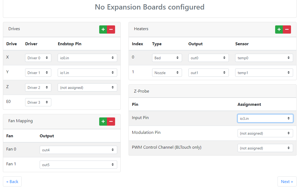
Firmware configuration for endstop pin
-
@emanuele same applies, select one and It will be further configured later, I would suggest leaving IO_0 free as this is used for a paneldue or serial communication.
Use the wiring diagram for pin names and function.
https://duet3d.dozuki.com/Wiki/Duet_3_Mainboard_6HC_Wiring_DiagramFollow my adventures in 3D Printing, laser cutting and electronics. https://linktr.ee/Rushmere3D
-
Ok Rushmere!
Thankyou for your help (I'm really confused!)
So you suggest something like this? It's correct? Can I proceed with the next step?
-
@emanuele I wrote a guide recently for the configuration tool. Does it help?
https://docs.duet3d.com/en/How_to_guides/Configuring_firmware#h-3-io-mappingI'm working on the wiring guide for the Duet 3, which would make this clearer. For wiring endstops on Duet 3, see https://docs.duet3d.com/User_manual/Connecting_hardware/Sensors_endstops
Ian
Bed-slinger - Mini5+ WiFi/1LC | RRP Fisher v1 - D2 WiFi | Polargraph - D2 WiFi | TronXY X5S - 6HC/Roto | CNC router - 6HC | Tractus3D T1250 - D2 Eth
-
@droftarts
Hi, thankyou for your help.
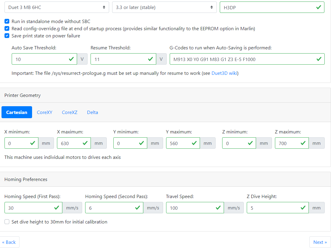
I read your guide but it's a little bit generic for my case.I'm building a big cartesian 3D printer with 1X, 2Y and 2Z leadscrews.
I want to pilot it in the simplest way (for the moment) so connected directly to a PC if possible.
I've two endstops on X and Y and a proximity sensor (LJ12A3-4-Z/BX) on Z.
I've a Dyzextruder PRO with a bowden configuration and a Dyze PRO hotend.I'm looking for somebody that can help me through the configuration tool: would you like to help me? If your answer is yes (I hope!) this is my first page completed:
If it is correct I will attach the second one and so on...
-
@emanuele said in Firmware configuration for endstop pin:
I'm building a big cartesian 3D printer with 1X, 2Y and 2Z leadscrews.
There are limitations on the configuration tool. You can only define one motor per axis. To configure the other motors to these axis, you will need to edit the config.g afterwards. See https://docs.duet3d.com/User_manual/Connecting_hardware/Motors_configuring#using-more-than-one-motor-on-an-axis-with-a-separate-driver-for-each-motor
@emanuele said in Firmware configuration for endstop pin:
I'm looking for somebody that can help me through the configuration tool: would you like to help me? If your answer is yes (I hope!) this is my first page completed:
Unfortunately I'm not around for the rest of the day, what with it being the weekend and having kids!
Ian
Bed-slinger - Mini5+ WiFi/1LC | RRP Fisher v1 - D2 WiFi | Polargraph - D2 WiFi | TronXY X5S - 6HC/Roto | CNC router - 6HC | Tractus3D T1250 - D2 Eth
-
@droftarts
No problem...when you've a second if you can look at these and give me back your feedback it will be really appreciated
Waiting for your reply!
-
@emanuele I'm not familiar with your probe. See https://docs.duet3d.com/User_manual/Connecting_hardware/Z_probe_connecting for types of probe supported and how to configure.
Do you have a PanelDue? If so, you'll need to keep io0 free for it, as it's only supported on this connection. So move your endstop assignments if necessary.
Otherwise, looks fine.Ian
Bed-slinger - Mini5+ WiFi/1LC | RRP Fisher v1 - D2 WiFi | Polargraph - D2 WiFi | TronXY X5S - 6HC/Roto | CNC router - 6HC | Tractus3D T1250 - D2 Eth
-
@droftarts
No, I don't have a panelDue (I want to pilot the 3D printer directly from the PC if possibile).
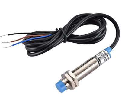
My proximity sensor is this one:
Ok if everything seems correct I'd like to send you the page 3:
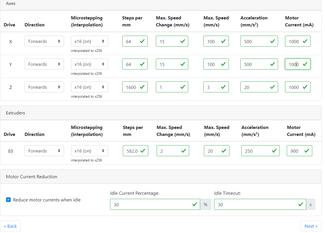
I've only a little doubt about the motor current: I've NEMA 23 and in the technical specification I see they are 2.8A; on the other hand I've found in this forum that for NEMA 23 we have to set 1000 mA. I'm confused...
-
@emanuele impossible to say what speeds and accelerations. That’s down to the individual machine, and testing. Set current at 60 to 80% of motor’s rated current.
Ian
Bed-slinger - Mini5+ WiFi/1LC | RRP Fisher v1 - D2 WiFi | Polargraph - D2 WiFi | TronXY X5S - 6HC/Roto | CNC router - 6HC | Tractus3D T1250 - D2 Eth
-
@droftarts
Sorry Ian, just to be sure (I don't want to cook my NEMA 23); this is the technical paper: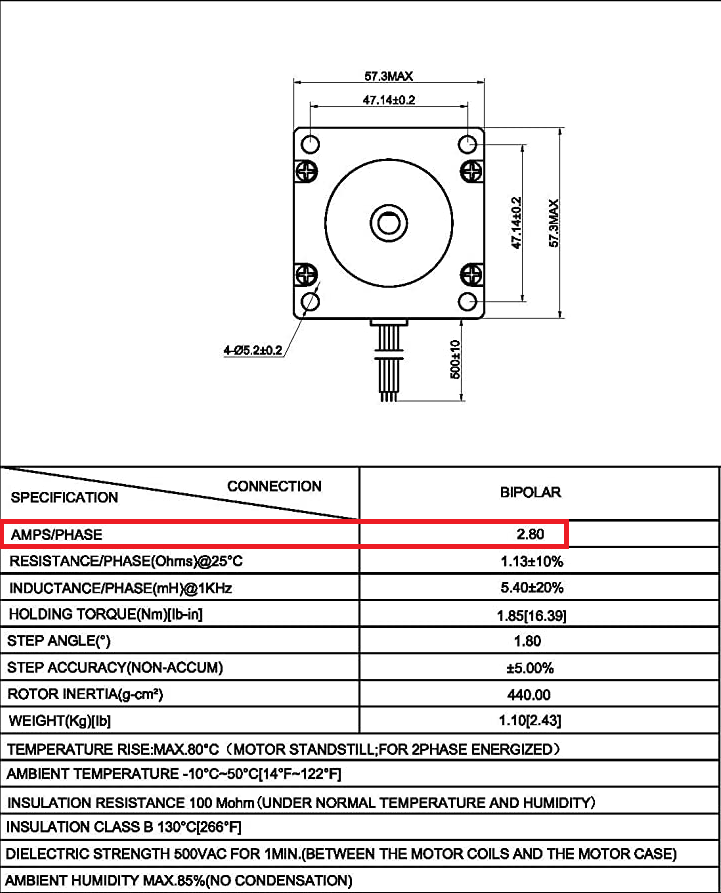
so 2,8 * 70% we can say 2000mA, right?
-
@emanuele that should be fine. Once powered up, give the motor a workout, and monitor it’s temperature. It should barely get warm to the touch. I’m slightly concerned about your earlier comment that you read somewhere the current should be set to 1A; it’s possible they meant that it needs to be set to at least 1A. You just can’t trust anything you read in forums!
Ian
Bed-slinger - Mini5+ WiFi/1LC | RRP Fisher v1 - D2 WiFi | Polargraph - D2 WiFi | TronXY X5S - 6HC/Roto | CNC router - 6HC | Tractus3D T1250 - D2 Eth
-
Thankyou for your help Ian.
I've downloaded the config.zip.
Now I need to add a second axis for Z and Y:
I've read
https://docs.duet3d.com/User_manual/Connecting_hardware/Motors_configuring#using-more-than-one-motor-on-an-axis-with-a-separate-driver-for-each-motor
but it's not so clear what I've to do.Can you explain me better what I've to change and in which file?
Thankyou so much!
-
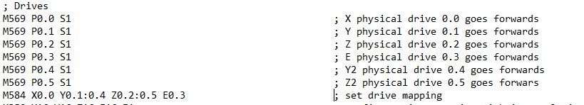
@emanuele in config.g, define the driver each second motor is connected to with M569. Then add the extra drivers to the axis in M584. So if you have:
M569 P0.0 S0
M569 P0.1 S0
M569 P0.2 S0
M569 P0.3 S0

M584 X0.0 Y0.1 Z0.2 E0.3
Then add
M569 P0.4 S0 ; second Y drive
M569 P0.5 S0 ; second Z drive
And change M584
M584 X0.0 Y0.1:0.4 Z0.2:0.5 E0.3Note that RepRapFirmware does not support individual motor settings where an axis has multiple motors connected to different stepper drivers. The first parameter specified will be used for all motors on the axis. You should use identical motors on any axis that has more than one motor to avoid unexpected behaviour.
However, each extruder axis (E) is treated as a separate axis, and specific settings for each extruder should be configured.
This means you can leave speed and acceleration settings as they are. See the configuration section lower down the page you linked for more details.Ian
Bed-slinger - Mini5+ WiFi/1LC | RRP Fisher v1 - D2 WiFi | Polargraph - D2 WiFi | TronXY X5S - 6HC/Roto | CNC router - 6HC | Tractus3D T1250 - D2 Eth
-
@droftarts
Like this?
If it is correct I've finished! And that's because of you!
I'd like to share with you my project: it has a volume of 560X630X700 mm with a Dyzend pro hotend and a DyzExtruder pro, and as you know two Z and 2 Y axis, each one with a NEMA 23 motor.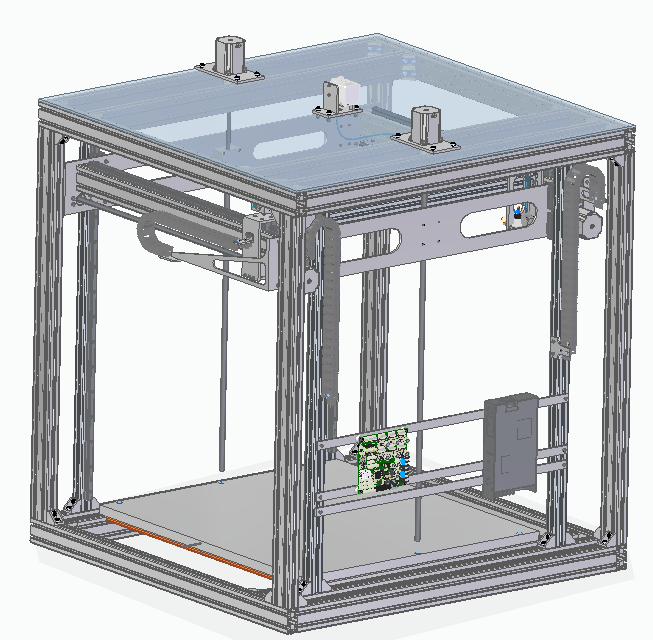
It is inspired to this:
https://3ddistributed.com/3d-printers/workhorse-printer/I hope you like it (it's a bit expensive but ok this is my hobby).
Waiting for your comments... -
@emanuele said in Firmware configuration for endstop pin:
Like this?
Yes, that looks correct. You may need to switch the direction of the motor, using the M569 S parameter (0 or 1), so they work together in the same direction.
There is a (recently written) commissioning guide here: https://docs.duet3d.com/en/How_to_guides/Commissioning
Ian