NEMA 23 Drama
-
@joaquin_suave said in NEMA 23 Drama:
i go into the RRF config tool and create a new zip file the download it in "my printer".
Once you have everything in the printer the first time, I'd suggest just modifying the config in place via the web editor.
The config tools does a good job of a general setup but then you really need to do the "fine tuning" for your specific machine by hand.
I actually save the entire config for each machine on another PC (in fact on network storage) and edit files there, then drop the updated file(s) back on the machine via the DWC web page.
That way if anything goes wrong during an update, I can just drop the whole lot back on a new SD card setup via DWC and it's working again straight away, with no messing about.
-
Here is my latest test and still no luck:
; Configuration file for Duet 3 (firmware version 3.3)
; executed by the firmware on start-up
;
; generated by RepRapFirmware Configuration Tool v3.3.10 on Fri Mar 18 2022 10:57:30 GMT-0700 (Pacific Daylight Time); General preferences
M575 P1 S1 B57600 ; enable support for PanelDue
G90 ; send absolute coordinates...
M83 ; ...but relative extruder moves
M550 P"My Printer" ; set printer name; Network
M552 P0.0.0.0 S1 ; enable network and acquire dynamic address via DHCP
M586 P0 S1 ; enable HTTP
M586 P1 S0 ; disable FTP
M586 P2 S0 ; disable Telnet; Drives
M569 P0.1 S1 ; physical drive 0.1 goes forwards
M569 P0.2 S1 ; physical drive 0.2 goes forwards
M569 P0.3 S1 ; physical drive 0.3 goes forwards
M569 P0.0 S1 ; physical drive 0.0 goes forwards
M584 X0.1 Y0.2 Z0.3 E0.0 ; set drive mapping
M350 X1 I0 ; configure microstepping without interpolation
M350 Y16 Z16 E16 I1 ; configure microstepping with interpolation
M92 X200.00 Y1.50 Z266.00 E100.00 ; set steps per mm
M566 X6000.00 Y900.00 Z60.00 E120.00 ; set maximum instantaneous speed changes (mm/min)
M203 X30000.00 Y6000.00 Z180.00 E1200.00 ; set maximum speeds (mm/min)
M201 X500.00 Y500.00 Z20.00 E250.00 ; set accelerations (mm/s^2)
M906 X2000 Y800 Z800 E800 ; set motor currents (mA)
M84 S0 ; Disable motor idle current reduction; Axis Limits
M208 X0 Y0 Z0 S1 ; set axis minima
M208 X416 Y416 Z400 S0 ; set axis maxima; Endstops
M574 X1 S1 P"null" ; configure switch-type (e.g. microswitch) endstop for low end on X via pin null
M574 Y1 S1 P"null" ; configure switch-type (e.g. microswitch) endstop for low end on Y via pin null; Z-Probe
M558 P0 H5 F120 T6000 ; disable Z probe but set dive height, probe speed and travel speed
M557 X15:215 Y15:195 S20 ; define mesh grid; Heaters
M308 S0 P"temp0" Y"thermistor" T100000 B4138 ; configure sensor 0 as thermistor on pin temp0
M950 H0 C"out0" T0 ; create bed heater output on out0 and map it to sensor 0
M307 H0 B1 S1.00 ; enable bang-bang mode for the bed heater and set PWM limit
M140 H0 ; map heated bed to heater 0
M143 H0 S120 ; set temperature limit for heater 0 to 120C
M308 S1 P"temp1" Y"thermistor" T100000 B4138 ; configure sensor 1 as thermistor on pin temp1
M950 H1 C"out1" T1 ; create nozzle heater output on out1 and map it to sensor 1
M307 H1 B0 S1.00 ; disable bang-bang mode for heater and set PWM limit
M143 H1 S280 ; set temperature limit for heater 1 to 280C; Fans
M950 F0 C"out8" Q500 ; create fan 0 on pin out8 and set its frequency
M106 P0 S0 H-1 ; set fan 0 value. Thermostatic control is turned off
M950 F1 C"out7" Q500 ; create fan 1 on pin out7 and set its frequency
M106 P1 S1 H1 T45 ; set fan 1 value. Thermostatic control is turned on; Tools
M563 P0 D0 H1 F0 ; define tool 0
G10 P0 X0 Y0 Z0 ; set tool 0 axis offsets
G10 P0 R0 S0 ; set initial tool 0 active and standby temperatures to 0C; Custom settings are not defined
-
@joaquin_suave
That config makes no sense?
It has X with 200 steps per mm, but Y with 1.5 steps per millimetre!!Are all the motors the same - and are you connecting the NEMA23 motors with two reds as one winding and two green as the other?
-
Oops My bad!
I am only testing the motor (nema 23) with the X drive and have set it so that when I manually move 1 mm it should turn the shaft 1 revolution. I figured that once i have achieved that I can tune the X & Y drives correctly.
Z and E are nema 17's and I don't seem to have any issues with them.
Any test setting you guys can suggest will be GREATLY appreciated!!!!
-
So your motor is 200 full steps per revolution. But you have microstepping set to 16, which means that "steps" to the FW are 16 * 200 = 3200 steps per revolution. Instructing it to turn 1mm should get you 200microsteps, or 1/16 revolution.
Does not explain why your NEMA 17's are behaving properly (maybe they don't support microstepping?)
-
@joaquin_suave said in NEMA 23 Drama:
M584 X0.1 Y0.2 Z0.3 E0.0 ; set drive mapping
M350 X1 I0 ; configure microstepping without interpolation
M350 Y16 Z16 E16 I1 ; configure microstepping with interpolation
M92 X200.00 Y1.50 Z266.00 E100.00 ; set steps per mm
M566 X6000.00 Y900.00 Z60.00 E120.00 ; set maximum instantaneous speed changes (mm/min)
M203 X30000.00 Y6000.00 Z180.00 E1200.00 ; set maximum speeds (mm/min)
M201 X500.00 Y500.00 Z20.00 E250.00 ; set accelerations (mm/s^2)
M906 X2000 Y800 Z800 E800 ; set motor currents (mA)
M84 S0 ; Disable motor idle current reductionI am only trying to configure X for right now (the X & Y motors are identical).
Z is a nema 17 with a leadscrew and is moving correctly as for as I can tell ( without using a test indicator), E is a nema 17 and moves the filament close to the correct length.
Wiring:
A2: Green
A1: Green/ White
B2: Red
B1: Red/ White -
I GOT IT!!!!!
I didn't have enough current for the motors! Now I will start fine tuning!
Thank all you SO MUCH!
-
undefined Phaedrux has marked this topic as solved 18 Mar 2022, 22:27
-
@joaquin_suave I was going to suggest that your jerk/maximum instantaneous speed of X6000 may be a problem. 6000mm/min is 100mm/s; larger motors may have a problem starting at this speed and require a lot of current to do it. Any move request at under 100mm/s would immediately be trying to run at that speed. High jerk is generally considered bad; better to have low jerk and higher acceleration, though you've also set that pretty high too. Minimum jerk should be 5mm/s, or 300mm/m, and a sensible value is 600 to 900mm/m.
I was also going to ask how you were actually testing the motor; just pressing the jog buttons in DWC, or sending a gcode command with a feedrate? Note you can change the feedrate of the DWC jog buttons in Settings > Machine specific > General > Machine specific > Feedrate for move buttons. See https://docs.duet3d.com/User_manual/Reference/Duet_Web_Control_Manual#general-tab-1
Ian
-
Well I spoke too quickly!
I did one test run @ 16x : 150 steps/ sec. : 15 change: 200mm/ sec. : 500 Accl :
5000 current... And the motor shaft rotated without stalling.Since then I have done +/- 60 tests WITH NO LUCK (in every imaginable configuration).
I disconnected the motor from the board and wired it up to a simple driver i have and it works just fine!?!?
Can anyone give a starting point to configure the drives for these motors?
Intelligent Motion Systems M-2231-2.4S (nema 23)
And I desire to achieve this travel:
79.8mm = 1 rotation of the pinion on the rack / the timing belt gear reduction of 3.75:1 = 21.28mm for 1 revolution of the motor shaft.Or at 1X (200 steps) = 9.398 steps/ mm.
Or at 16X (3200 steps) = 150.368 steps/ mm.Could there be a possibility that i am just asking too much from the drivers?
Could there be a possibility that i "fried" the drivers?
Could there be a possibility that i can wire in "add-on" drivers?In the worst case scenario, I could tear the machine apart and replace the rack/ pinion w/reduction to a regular belt drive. If so, what is a "comfortable" mm to shaft ratio?
I am not trying to break any "speed records", but rather trying to repurpose a really nicely made (expensive) piece of hardware, learn about controls, 3D printing.
I can't say that I have been very successful so far!
-
undefined Phaedrux has marked this topic as unsolved 21 Mar 2022, 21:10
-
@joaquin_suave said in NEMA 23 Drama:
ntelligent Motion Systems M-2231-2.4S
Do you have the specs for the motor? Googling comes up with several and I don't know which matches yours.
-
Holding Torque: 2.39 oz-in (169 N-cm)
Phase Current: 2400 ma
Leads: 4
Phase resistance: 1.5 Ohms
Phase Inductance: 5.4 mH
Detent Torque 9.7 oz-in (6.9 N_cm)
Rotor Inertia: .0065 oz-in-sec2 (.46 kg-cm2)
Length: 2.99" (7.6 cm)
Weight: 35.3 oz (1 kg)Thanks again for your help!
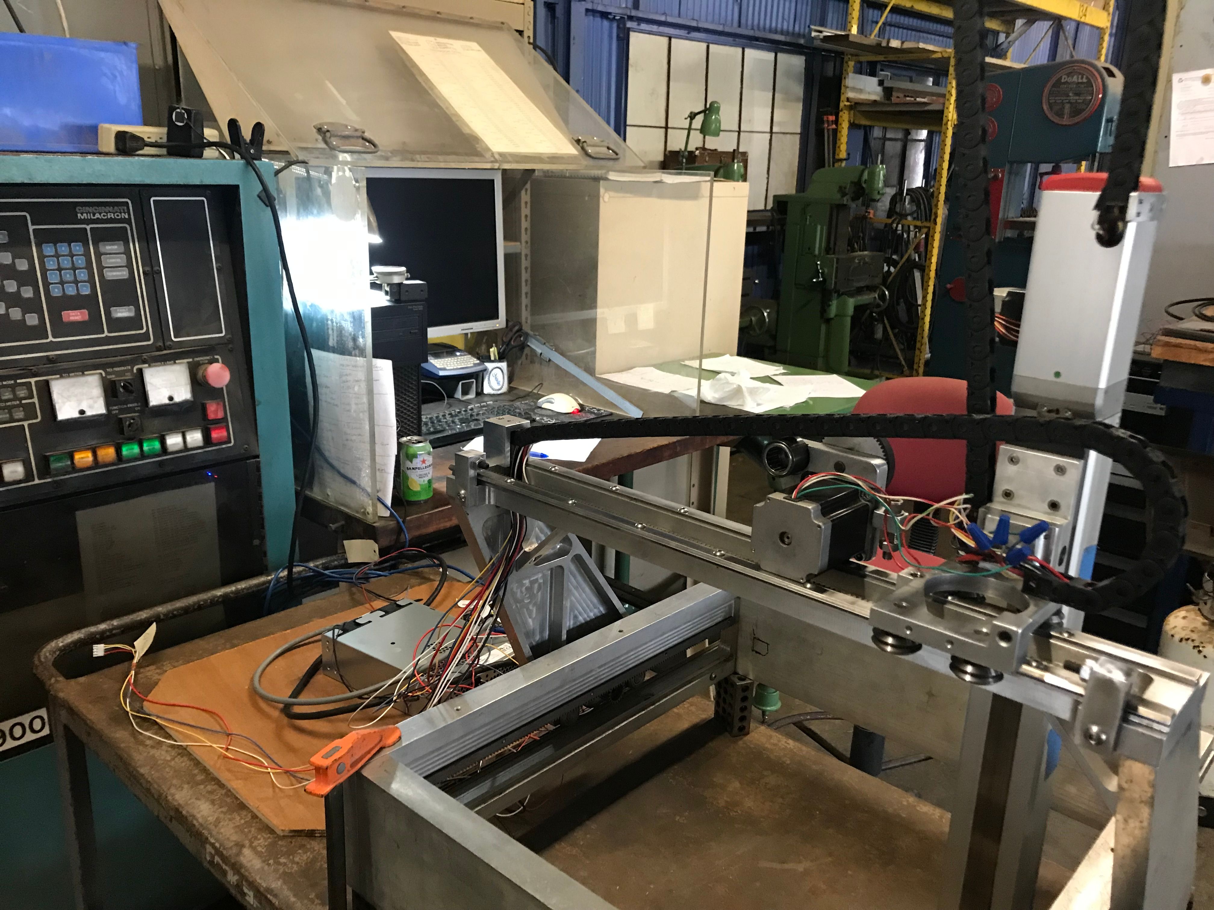
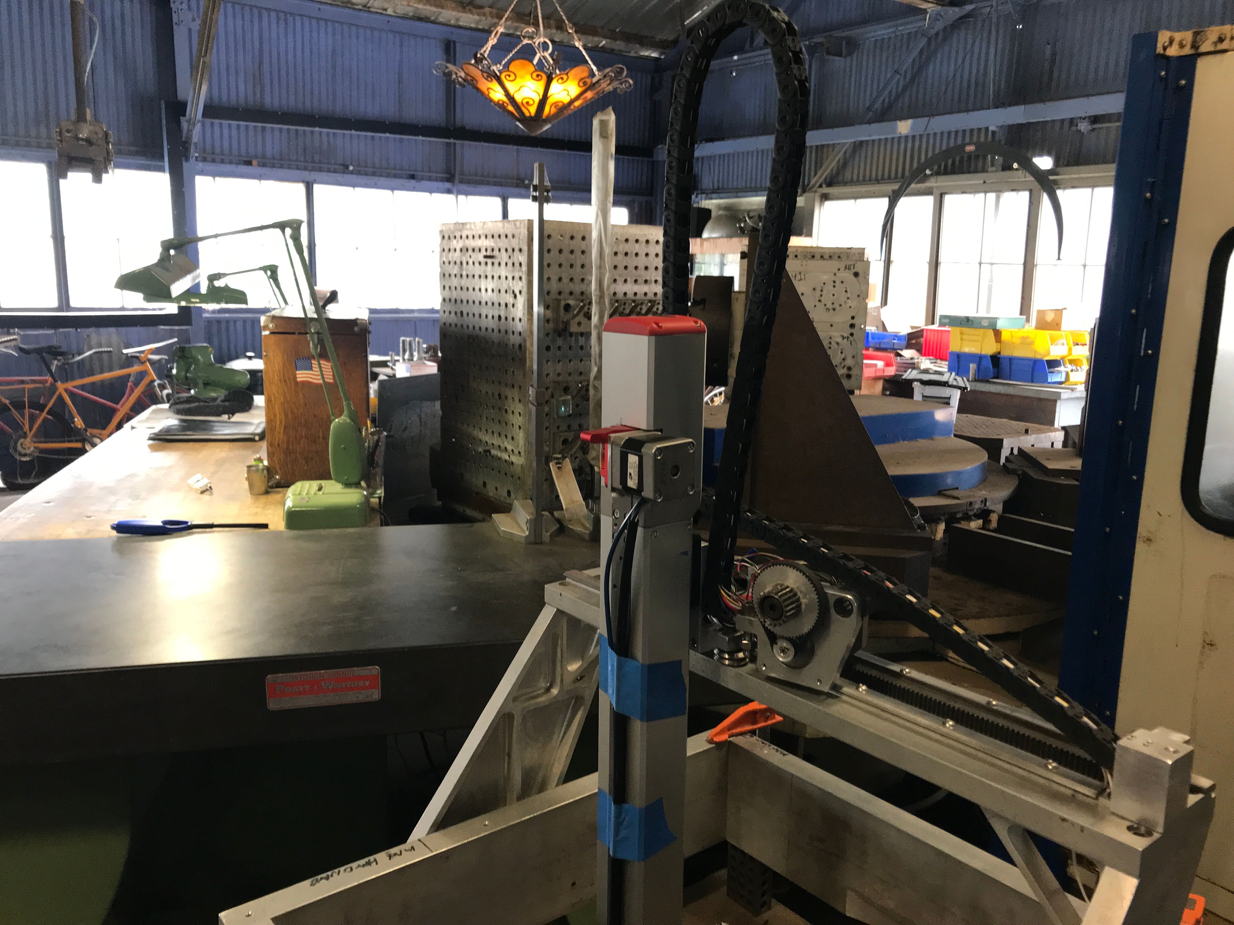
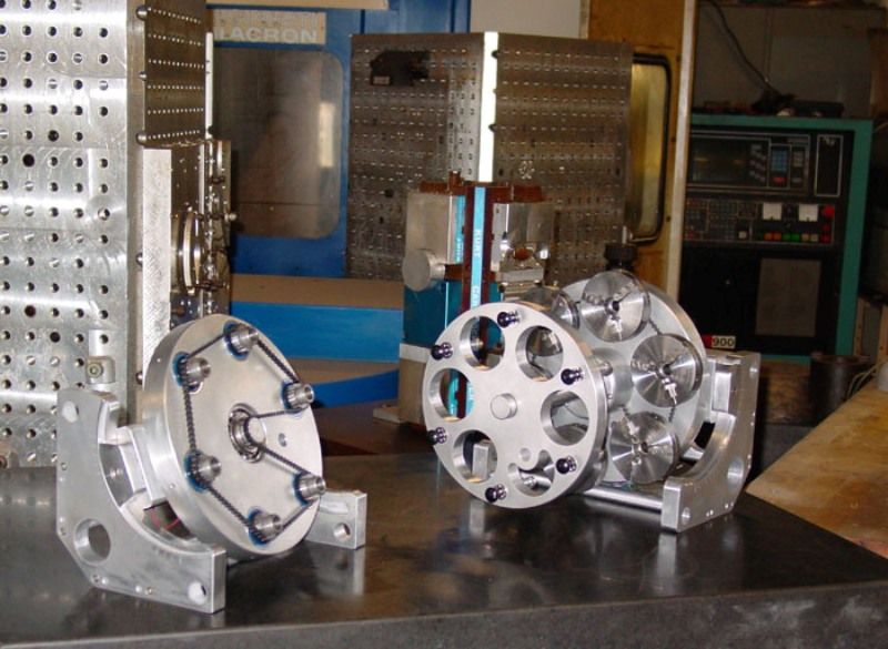
Here are a couple of more pictures:


-
@joaquin_suave excuse me if I overlook that someone already mentioned it:
In this environment, I would ground all stepper casings with a star formed grounding to protect against static charging.
-
You might like to have a play with the EMF calculator here
-
Thanks for the recent advice Guys,
I grounded the metal table that device is being developed on the power cord ground and to the giant mill behind it in the pictures.
No Luck!
I played around a bit with the EMF calculator. I added the spec's of the motor, tried max travel as low as 60 mm a second with nothing connected to the motor shaft and am still stalling the motor.
An advice on the "ball park" values I'm looking for would be greatly appreciated!
So at this time I am going to keep trying different configurations, but more importantly I am going to GUT my X and Y drive systems then design and build belt drive replacements ( It helps to have a 5 axis CNC shop at one's disposal).
So a couple of quick questions about belt drives for 3D printers:
What is the "typical" mm/step travel (@ 1x, @ 16x )? I'll do the math from there to get the pulley size.
Are there "off the shelf" belt clamps (I'll be using GT3 3/mm belts)?
I have designed and built A BUNCH of belt driven devices but have always been the "mechanical guy" and worked with the "electronic people" of the companies/ DOD to integrate my devices into their equipment. The only previous experience I have had was with CNC4pc motion controller and it was child's play.
-
@joaquin_suave can you post your current config.g, to show motor settings, and explain where you are connecting the Nema 23 motors (I think to X axis)? As I said previously, I think you had the ‘instantaneous speed’ set to 6000mm/min, ie the motors are trying to start at 100mm/s. Try 600.
Also, your acceleration on X was set to 30000; try 2000.
Ian
-
@joaquin_suave said in NEMA 23 Drama:
grounded the metal table that device is being developed on the power cord ground and to the giant mill behind it in the pictures.
This is not what I meant. I mean ground the casing of the steppers itself. The belts build up static charge, which should be discharged. Aluminium (= oxidized and isolator) or plastic mounting will not discharge, linear guides and carriages are lubricated may isolate also.
-
Hello: My name is Joaquin Suave and I am a .... BONEHEAD!!!!
Being the lazy old curmudgeon that I am, I have been doing all my code modifications in the RRF config tool. Being around machine controls for longer than most of you "pups" have been alive, I "assumed" that when the control was unplugged that it would do a reboot and the upload from the config tool would change my settings... OOPS!
This morning I opened the config.g file and it looked NOTHING like the edits I have been trying for the last 3 weeks! I manually entered my original mm/ step and droftarts suggestions (thanks again!) and the motor shaft turned!
I put the belt back on the reduction drive: WORKED FINE!
Reattached the X motor/drive to the X carriage: AND IT MOVES LIKE A CHARM!!!"Bolted" the Y drive back together: AND ROCK & ROLL BABY!!!
My problem is solved! Thank you all again for you patience & help!!!
-
So this is where I am at right now:
; Configuration file for Duet 3 (firmware version 3.3)
; executed by the firmware on start-up
;
; generated by RepRapFirmware Configuration Tool v3.3.10 on Sat Mar 05 2022 11:18:10 GMT-0800 (Pacific Standard Time); General preferences
M575 P1 S1 B57600 ; enable support for PanelDue
G90 ; send absolute coordinates...
M83 ; ...but relative extruder moves
M550 P"My Printer" ; set printer name; Network
M552 P0.0.0.0 S1 ; enable network and acquire dynamic address via DHCP
M586 P0 S1 ; enable HTTP
M586 P1 S0 ; disable FTP
M586 P2 S0 ; disable Telnet; Drives
M569 P0.1 S1 ; physical drive 0.1 goes forwards
M569 P0.2 S1 ; physical drive 0.2 goes forwards
M569 P0.3 S1 ; physical drive 0.3 goes forwards
M569 P0.0 S1 ; physical drive 0.0 goes forwards
M584 X0.1 Y0.2 Z0.3 E0.0 ; set drive mapping
M350 X4 Y4 I0 ; configure microstepping without interpolation
M350 X16 Y16 Z16 E16 I1 ; configure microstepping with interpolation
M92 X154.50 Y154.50 Z262.00 E420.00 ; set steps per mm
M566 X1800.00 Y1800.00 Z1000.00 E120.00 ; set maximum instantaneous speed changes (mm/min)
M203 X12000.00 Y12000.00 Z1000.00 E1200.00 ; set maximum speeds (mm/min)
M201 X500.00 Y500.00 Z500.00 E250.00 ; set accelerations (mm/s^2)
M906 X4800 Y4800 Z1800 E800 I30 ; set motor currents (mA) and motor idle factor in per cent
M84 S30 ; Set idle timeout; Axis Limits
M208 X0 Y0 Z0 S1 ; set axis minima
M208 X416 Y416 Z400 S0 ; set axis maxima; Endstops
; WARNING: No endstops configured; Z-Probe
M558 P0 H5 F120 T12000 ; disable Z probe but set dive height, probe speed and travel speed
M557 X15:215 Y15:195 S20 ; define mesh grid; Heaters
M308 S0 P"temp0" Y"thermistor" T100000 B4138 ; configure sensor 0 as thermistor on pin temp0
M950 H0 C"out0" T0 ; create bed heater output on out0 and map it to sensor 0
M307 H0 B1 S1.00 ; enable bang-bang mode for the bed heater and set PWM limit
M140 H0 ; map heated bed to heater 0
M143 H0 S120 ; set temperature limit for heater 0 to 120C
M308 S1 P"temp1" Y"thermistor" T100000 B4138 ; configure sensor 1 as thermistor on pin temp1
M950 H1 C"out1" T1 ; create nozzle heater output on out1 and map it to sensor 1
M307 H1 B0 S1.00 ; disable bang-bang mode for heater and set PWM limit
M143 H1 S300 ; set temperature limit for heater 1 to 300C; Fans
M950 F0 C"out8" Q500 ; create fan 0 on pin out8 and set its frequency
M106 P0 S1 H-1 ; set fan 0 value. Thermostatic control is turned off
M950 F1 C"out7" Q500 ; create fan 1 on pin out7 and set its frequency
M106 P1 S1 H1 T45 ; set fan 1 value. Thermostatic control is turned on; Tools
M563 P0 D0 H1 F0 ; define tool 0
G10 P0 X0 Y0 Z0 ; set tool 0 axis offsets
G10 P0 R0 S0 ; set initial tool 0 active and standby temperatures to 0C; Custom settings are not defined
-
undefined Phaedrux has marked this topic as solved 29 Mar 2022, 04:50