Belt Driven Carriage Movement
-
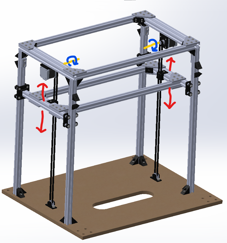
I'm attempting to add an extra axis to a machine to control a carriage that moves parallel to the Z-axis on the printer. It's driven by two belt-connected steppers which move in the opposite directions. I'm hoping to use drive 5 and 6 on my Duet 2 wifi and Duex 5. However I'm still very much a beginner and was hoping for a second set of eyes on and tell me if I set it up right. I struggled to understand when to use nnn vs. nnn:nnn and what all I need besides it setup properly in config.g and my homev.g files.
; Configuration file for Duet WiFi (firmware version 3.3)
; executed by the firmware on start-up
;
; generated by RepRapFirmware Configuration Tool v3.3.10 on Sun Jan 09 2022 20:46:24 GMT+0100 (Централноевропейско стандартно време)

; General preferences
M575 P1 S1 B57600                               ; enable support for PanelDue
G90                                             ; send absolute coordinates...
M83                                             ; ...but relative extruder moves
M550 P"RL1 Proto"                              ; set printer name

; Network
M551 P"SkiBum98"								; set password
M552 S1                                         ; enable Wifi
M586 P0 S1                                      ; enable HTTP
M586 P1 S0                                      ; disable FTP
M586 P2 S0                                      ; disable Telnet

; Drives
M569 P0 S1                                      ; physical drive 0 goes forwards (eventually X)
M569 P1 S1                                      ; physical drive 1 goes forwards (eventually Y)
M569 P2 S1                                      ; physical drive 2 goes forwards (eventually Z)
M569 P3 S1                                      ; physical drive 3 goes forwards (eventually E)
M569 P4 S1										; physical drive 4 goes forwards (eventually U)
M569 P5 S1										; physical drive 5 goes forwards (eventually V1)
M569 P6 S0										; physical drive 6 goes backwards (eventually V2)

; Motor Speeds and Accelerations
M584 X0 Y1 Z2 E3 U4 V5:6                               ; set drive mapping

M350 X16 Y16 Z16 E64 U16 V16 I0                      ; configure microstepping without interpolation
M92 X80.00 Y80.00 Z400.00 E80.00 U400.00 V80.00        ; set steps per mm
M566 X900.00 Y900.00 Z60.00 E120.00 U60.00 V700.00     ; set maximum instantaneous speed changes (mm/min)
M203 X6000.00 Y6000.00 Z180.00 E1200.00 U180.00 V4000.00 ; set maximum speeds (mm/min)
M201 X500.00 Y500.00 Z20.00 U20.00 E250.00 U20.00 V250.00     ; set accelerations (mm/s^2)
M906 X800 Y800 Z800 E800 U800 I30                ; set motor currents (mA) and motor idle factor in per cent

; Axis Limits
M208 X0 Y0 Z0 U0 V0 S1                                ; set axis minima
M208 X230 Y210 Z200 U600 V400 S0                          ; set axis maxima

; Endstops
M574 X1 S3                                      ; configure sensorless endstop for low end on X
M574 Y1 S3                                      ; configure sensorless endstop for low end on Y
M574 Z1 S2 			                            ; configure Z-probe endstop for low end on Z
M574 U1 S1 P"e0stop"                            ; configure switch-type (e.g. microswitch) endstop for low end on U via pin estop
M574 V1 S3 										; configure sensorless endstop for low end on V

M915 X Y R0 F0

; Z-Probe
M950 S0 C"io4.out"              ; create servo pin 0 for BLTouch (use IO_4/5/7 for 6HC, IO_1/2/3 for Mini 5+)
M558 P9 C"io4.in" H5 F120 T6000 ; set Z probe type to bltouch and the dive height + speeds
G31 P500 X25 Y0 Z2.5            ; set Z probe trigger value, offset and trigger height
M557 X15:215 Y15:195 S20        ; define mesh grid
M557 X15:215 Y15:195 S20                        ; define mesh grid

; Heaters
M308 S1 P"e1temp" Y"thermistor" T100000 B4138   ; configure sensor 1 as thermistor on pin e0temp
M950 H1 C"out1" T1                            ; create nozzle heater output on e0heat and map it to sensor 1
M307 H1 B0 S1.00                                ; disable bang-bang mode for heater  and set PWM limit
M143 H1 S280                                    ; set temperature limit for heater 1 to 280C

M308 S2 P"e2temp" Y"thermistor" T100000 B4138   ; configure sensor 2 as thermistor on pin e1temp
M950 H2 C"e2out" T2                            ; create chamber heater output on e1heat and map it to sensor 2
M307 H2 B1 S1.00                                ; enable bang-bang mode for the chamber heater and set PWM limit
M141 H2                                         ; map chamber to heater 2
M143 H2 S280                                    ; set temperature limit for heater 2 to 280C

; Fans
M950 F0 C"fan0" Q500                            ; create fan 0 on pin fan0 and set its frequency (hot end)
M106 P0 S1 H-1                                  ; set fan 0 value. Thermostatic control is turned off
M950 F1 C"fan1" Q500                            ; create fan 1 on pin fan1 and set its frequency (nozzle)
M106 P1 S1 H1:2 T45                             ; set fan 1 value. Thermostatic control is turned on

; Tools
M563 P0 D0 H1 F0                  ; define tool 0
G10 P0 X0 Y0 Z0                                 ; set tool 0 axis offsets
G10 P0 R0 S0

M563 P1 D0 H1 F0                  ; define tool 1
G10 P0 X0 Y0 Z0                                 ; set tool 0 axis offsets
G10 P0 R0 S0

; Epilogue
M556 S100 X0 Y0 Z0                                 ; Put your axis compensation here
M912 P0 S0                                         ; Put your CPU temperature sensor correction here
M501                                               ; load saved parameters from non-volatile memory
M911 S10 R11 P"M913 X0 Y0 G91 M83 G1 Z3 E-5 F1000" ; set voltage thresholds and actions to run on power loss
T0                                                 ; select first tool
; Custom settings are not defined
; Home V at the high end of the axis M400 M913 V70 ; drop motor current to 70% M400 G91; relative positioning G1 H1 V240 F10000 ; move quickly to V axis endstop and stop there (first pass) G1 H2 V-5 F12000 ; go back a few mm G1 H1 V240 F7000 ; move slowly to X axis endstop once more (second pass) G90 ; absolute positioning M400 M913 X100 Y100 ; return current to 100% M400 -
I haven't looked at your configuration yet, but you will very likely require either geared drives or a brake for your extra gantry to be held when the motors are disabled.
-
@oliof you are right :), this is being worked on the side as we speak, but hoping to keep making progress on the firmware too
-
Quick note:
M574 Z1 S2is unneccessary, drop it. This setting is for axes other than Z that use a probe as endstop sensor.I am not entirely sure what your U axis is for, so that part may or may not be right.
In the homev.g file you may want to set the stepper to spreadcycle in the beginning (
M569 P5 D2, same for P6) and return to normal hybrid mode at the end. You also don't seem to set stall detect for V, so you would need to addM915 V R0 F0before or after switching the stepper mode (you have an M915 in config.g but only for X and Y). You will also need to tune stall detection threshold and set that (S parameter for M915).<>RatRig V-Minion Fly Super5Pro RRF<> V-Core 3.1 IDEX k*****r <> RatRig V-Minion SKR 2 Marlin<>
-
@jrcl I use a 30:1 worm gear drive unit to lift the bed in my printer. The motor/gear box is mounted at the bottom of the frame with an 8mm shaft that goes through the gear box and drives two pulleys which lift the bed with belts. It doesn't move when the power to the motor is cut. By using a single motor, the gantry or bed won't tilt when power is reapplied to the motor.
This is the motor/gearbox: https://www.ebay.com/itm/191714031261?epid=711126295&hash=item2ca30bf69d:g:A7UAAOSwPhdVB2f0
I priced out options for motors with brakes and found the motor/gearbox was cheaper.
I used two linear guides, but it should work fine with wheels on t-slot, too.
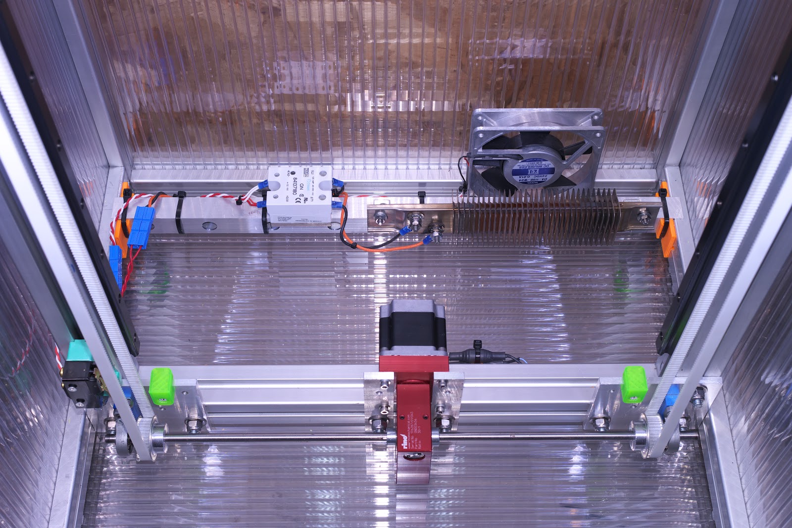
The photo shows steel core belts which I have replaced with glass core belts. I measured the stretch of both the steel core and glass core belts and found that it is small enough not to matter. I ended up using 60 tooth drive pulleys which yields 20 um per full step of the 200 step/rev motor. IRIC, it's driven with 16:1 ustepping and maximum speed is about 15 mm/sec.
-
@mrehorstdmd Great solution! Unfortunately, most of the packaging space is taken up in the rest of the machine that isn't shown in the clip above. Luckily we already made a little adjustable brake system to take care of it for the time being since we posted. Super clean setup though, love it!
-
@oliof said in Belt Driven Carriage Movement:
Quick note:
In the homev.g file you may want to set the stepper to spreadcycle in the beginning (M569 P5 D2, same for P6) and return to normal hybrid mode at the end.What is normal hybrid mode? Is that a D parameter?
-
@jrcl from the documentation:
The default is spreadCycle for TMC2660, TMC2160 and TMC516x drivers, and stealthChop2 for TMC22xx. In stealthChop mode the drivers will switch over to spreadCycle automatically at high speeds, see the V parameter.
I called this hybrid mode but you can make it not switch to spreadcycle by setting the V parameter so the switch over never happens within speeds the machine is limited to.