how to control a relay with the duet 2
-
how do i control a relay with the duet 2 to switch a cnc compatible plasma cutter to turn on and off?
any help would great cheers mike -
@mike8761 It would depend on how you wanted to control it, but I believe there are multiple ways of connecting it to the board, I use fan ports to control relays for simple on/off but you can use IO or heaters, like I said depends how you want to use it and what your not using on your board
")
-
@jumpedwithbothfeet
Hi thanks so much for the reply to my post i have a wiring diagram which is attached would it be possible to have a look at it and see if i am on the right track? the relay is for driving a cnc compatible plasma cutter just to turn on and off it has an imput avation type connector on the rear of the machine which has pins 1,2,3.and 4,
pins 1&2 are for firing the tourch i have tested this by touching the two wires from a 5v psu to pins 1&2 which fires the tourch and when removed tourch stops.
would be great if you could help. -
@mike8761 Hi Mike looking at the drawing I don't think it will work as you are trying to power the cutter with the relay, I made the same mistake
excuse the bad picture but this is like my setup minus the buck convertor, I don't know the voltages your using or the relay but hopefully it`ll give you an idea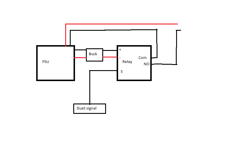
-
All the plasma systems I've seen are a dry contact to trigger the torch. ( i.e. you're just bridging the two pins on the plasma)
You probably should not be feeding voltage to them. -
@owend So it would be looking more like this?
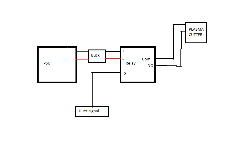
-
@jumpedwithbothfeet said in how to control a relay with the duet 2:
@owend So it would be looking more like this?
That should do the trick.
Typically the plasma will have two pins for the trigger and two for arc voltage feedback. There may also be an "arc established" signal.
Just be sure you don't connect the voltage feedback to the duet. -
@owend Hi there Owen thanks for your reply to the wiring for my plasma setup.
what i would like your help with is as follows:-
- i am presuming that i take one wire from the left hand pin on the fan0 conection to the (S) pin on the relay.
(2) what would i type in the CONFIG .G FILE to enable the fan/relay to turn on and off.
Thanks for your help
Mike -
Your config.g file should have have something like this
Refer to the docs for M950 and M42M950 P0 C"fan0" Q500To turn it on/off use
M42 P0 S1 ; turn on
M42 P0 S0 ; turn off
You'll need to ensure that the relay you use is suitable.
i.e. it must be 3.3v compatible.
Probably worth posting specs of the relay here.EDIT:
In the example I gave the fan pin will be configured as a GPIO pin.
My comments about 3.3v are because most GPIO pins are 3.3v and have low current capabilities.
If you use a fan or heater output and your VIN is compatible you may be able to control your relay directly from it.
On a plasma you're not likely to need a heated bed, so using a heater output makes sense. -
@owend Hi Owen getting a little lost how would you wire this up and config in the .g file.
if you could give me a diagram as well that would be excellent.
Where are you in the world , i am in the uk on the NW coast in a town called Southport about 20miles north of Liverpool.Cheers Mike
-
I'm in Brisbane, Australia.
You need to post the data sheet for the relay or module you want to use and details of your setup including what voltage you're running the duet on.Note: I've never used a duet for plasma. My experience is with commercial units.
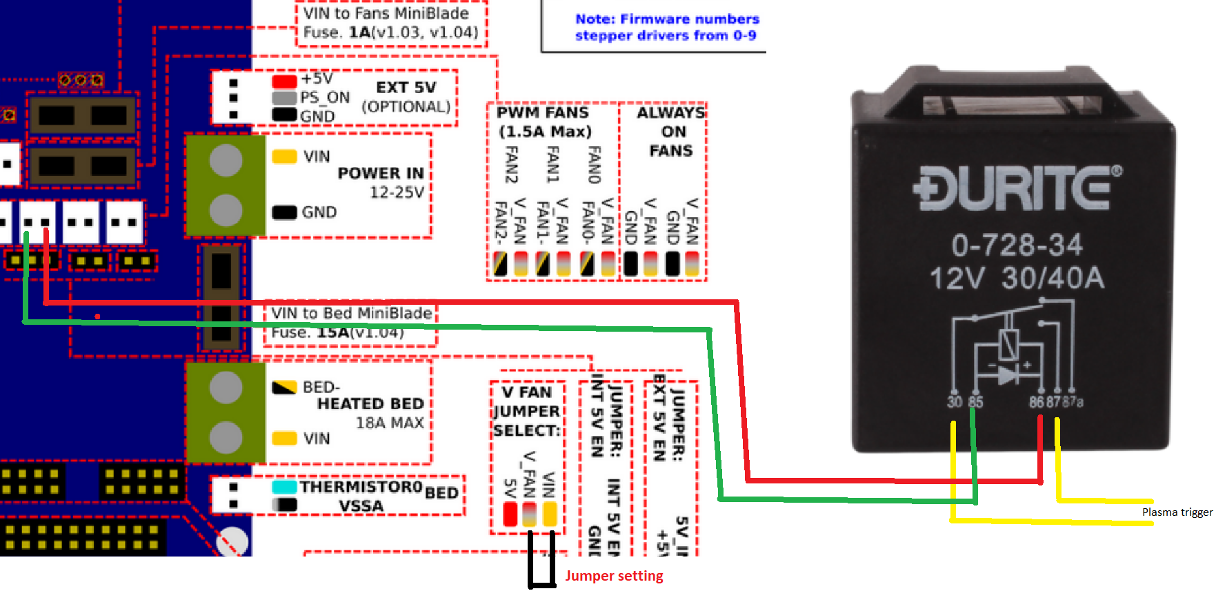
The easiest setup I would think is to use a relay the same voltage as your duet is powered by.
So if it's 12v then something like this should be fine.
https://www.12voltplanet.co.uk/mini-change-over-relay-12v-3040a-with-diode.htmlI believe the fan outputs on the later duet 2 have built in flyback protection diodes but the heater outputs do not, but someone with more knowledge can confirm.
The relay linked has a flyback diode.
The configuration should be as I listed above if you are using Firmware 3.0 or later.
M950 P0 C"fan0"And turn it on and off as required in your Gcode with M42
You'll need to adjust your post processor for this as a plasma controller would typically use M07 & M08M42 P0 S1 ; turn on M42 P0 S0 ; turn offI don't know how you will get a THC working.
There is M951 but I have no idea how to implement it from a hardware point of view.
Most cheaper CNC plasmas use a stand alone THC controller and a DC motor on the Z axis.
You would then configure another relay in a similar manner to allow you to turn on/off the THC as required in your Gcode. -
@owend
Hi Owen thanks for your help YOU ARE A TOP MAN
MAINS POWER IN = 240V TO PSU
V OUT OF PSU = 24V TO THE DUET BOARD
IT SAYS SOMWHERE IN THE DOCS THAT THE FAN OUTPUT WON'T TRIGGER A RELAY AS IT PUTS OUT 3.2V YOU CAN HOWEVER YOU CAN RUN A 12V FAN IF YOU REMOVE THE JUMPER AND USE A BUCK CONVERTER FROM PSU STEPPED DOWN TO 12V TO THE MIDDLE JUMPER PIN BELLOW THE FAN0 OUTPUT CONNECTOR.SO I HAVE ORDERED SOME 5V RELAYS AND 3.2 V RELAYS WHICH ARRIVE TO DAY FROM AMAZON, IF THEY WON'T WORK, I CAN USE THE ONE YOU SURGGEST
SO I THOUGHT I WOULD USE THIS (optocoupler relay 8 Channel Relay Module 8 Channel Optocoupler 3.3V Relay Module Board High & Low Trigger 12V (24V) )
WINGONEER 5PCS KY-019 5V One Channel Relay Module Board Shield for PIC AVR DSP ARM for arduino Relay.
IT WON'T SEEM TO LET ME ATTCHE PICS FROM AMAZON ?HOPE THIS HELPS YOU TO HELP ME .
CHEERS MIKE
-
@mike8761 said in how to control a relay with the duet 2:
IT SAYS SOMWHERE IN THE DOCS THAT THE FAN OUTPUT WON'T TRIGGER A RELAY AS IT PUTS OUT 3.2V YOU CAN HOWEVER YOU CAN RUN A 12V FAN IF YOU REMOVE THE JUMPER AND USE A BUCK CONVERTER FROM PSU STEPPED DOWN TO 12V TO THE MIDDLE JUMPER PIN BELLOW THE FAN0 OUTPUT CONNECTOR.
I think you're confusing a couple of different things here.
You only need a buck converter if for example you wanted to run a 12v fan on a 24v powered duet.
And the fan outputs can't be 3.3v if you run a 12 or 24v fan on them?
The other GPIO pins do indeed output 3.3v.If you connect the fan jumper as I have indicated, you will have 24v output on the fan 0 connection and it is capable of handling 1A (total) maximum across all fan outputs.
The three PWM outputs have flyback diodes built in.
https://docs.duet3d.com/Duet3D_hardware/Duet_2_family/Duet_2_WiFi_Ethernet_Hardware_Overview#description-of-connectionsSo you could just use a 24v version of the relay I indicated
If you are using a relay module KY-019, they typically require 5v power.
So you could put the fan jumper between V_FAN and 5V and connect the relay to one of the always on fan connections. Note that this would make ALL the fan outputs 5v.
Alternately power it from 5v from somewhere else.
Your signal pin on the relay would go to any of the GPIO pins which would be configured and triggered the same way as above. -
@mike8761 said in how to control a relay with the duet 2:
SO I THOUGHT I WOULD USE THIS (optocoupler relay 8 Channel Relay Module 8 Channel Optocoupler 3.3V Relay Module Board High & Low Trigger 12V (24V) )
WINGONEER 5PCS KY-019 5V One Channel Relay Module Board Shield for PIC AVR DSP ARM for arduino Relay.I just realised you've listed both an 8 channel relay setup and a single channel relay module.
My comments apply only to the typical single channel module.
an 8 channel module is likely going to need more current than can be supplied directly from the duet.
As you haven't supplied specs for either you'll need to take care. -
@owend
HI OWEN I THINK I WILL JUST STICK TO THE SAME DIAGRAM PICTURE AND WIRING YOU SENT TO ME WITH THE SAME TYPE RELAY YOU SPECIFY AND THEN CONFIG THE CODE IN THE CONFIG.gfile AS YOU SHOW TO CONTROL FAN0 ON AND OFF .I WILL POSSIBLY SEND BACK OTHER RELAYS OR MAY KEEP HOLD OF THEM.
REGARDING THE T H C I MAY USE A FLOATING HEAD TYPE SETUP OR A PROBE FINGERS CROSSED.
THAANKS FOR ALL YOUR HELP
HAVE A GOODAY OR EVINING ALL THE BEST MIKE SPK SOON