@dc42 /Duet 3d : Toolboard 1LC OUT1 failure
-
Hello DC,
I bought my Toolboard 1LC form Filastruder almost 1 year ago, on the 26th of May 2021.Was slowly getting my HevORT build up to scratch -> see here: https://forums.hevort.com/viewtopic.php?f=17&t=585
Commissioned the Toolboard wrt Heaters, Z-Probe, X-limit switch, Extruder, temp sensor and hot-end fan on OUT2, F1 (fan1)in my code, which is a simple 2-wire 24V fan, runs great, no issues at all and set to turn on full @55deg C, to ensure I don't clog up the hot-end, which both the Dragon and Mosquito seems to suffer from if I don't switch it on asap - code below, working as expected, no dramas:
M950 F1 C"121.out2" Q500 ; create fan 1 on pin 121.out2 and set its frequency - 2-pin fan for cooling hot-end
M106 P1 T55 S1 H1 ; set fan 1 value. Thermostatic control is turned on - (H-1 turns it off)Now, the problem sits on my 4-wire PWM channel, OUT1 - it stays on hard, weather I use a 4-wire PWM fan, 24V, 12V versions, or, even a 3-wire 12V fan, as well as a 2-wire common fan - it is setup as F0 (Fan 0) in my code - rest assured, I have tried all iterations in trying to get to it change speed at all, even hard-off, nothing. Of course, I removed the ! for non-pwm fans, but still the same:
M950 F0 C"!121.out1+out1.tach" Q25000 ; create PWM fan 0 on pin 121.out1 and set its frequency - PWM 50mm fan for cooling printed parts
M106 P0 T45:75 H1 ; set fan 0 value to full speed. Thermostatic control is turned off (H-1 turns it off)
;M106 P0 S0 H-1 ; set fan 0 value. Thermostatic control is turned on by Heater 1 /Dragon hot-end
;M106 P0 T45 S1 H1As an electronics engineer myself, seems that the PWM MOSFET is probably failed 'shorted'. I had a quick look on the board, I cannot see any components that might have let the smoke out, nor do I find any dry solder joints on it in the components around the OUT1. My order number with Filastruder was ORDER #71157
Would you guys be able to get me sorted, please? Whilst I generally won't have issues to use it as is, in this case, the continuously running fan is driving me slightly mad, as well as causing first-layer adhesion probs. It is a great little board, luv the Accelerometer on it too, as it helped me tweak the ringing out of the prints....and I prefer using the Toolboard due to ease of wiring, as I don't really want to run a bunch of wires down to the 6HC mainboard.
Will appreciate your feedback.
Kind regards,
Phillip aka Beano -
@beano Raising this to the top, in case it was missed by Duet Staff.
-
@beano said in @dc42 /Duet 3d : Toolboard 1LC OUT1 failure:
Now, the problem sits on my 4-wire PWM channel, OUT1 - it stays on hard, weather I use a 4-wire PWM fan, 24V, 12V versions, or, even a 3-wire 12V fan, as well as a 2-wire common fan - it is setup as F0 (Fan 0) in my code - rest assured, I have tried all iterations in trying to get to it change speed at all, even hard-off, nothing. Of course, I removed the ! for non-pwm fans, but still the same:
Please post a photo showing how you have connected a 2-wire fan to the connector. It is easy to get always-on operation if you use the wrong pins.
Duet WiFi hardware designer and firmware engineer
Please do not ask me for Duet support via PM or email, use the forum
http://www.escher3d.com, https://miscsolutions.wordpress.com -
@dc42 @dc42 @dc42 : I have the (2-wire) fan wired red to OUT1:+VOUT, Black to OUT1:out1. If I check on the std 3-wire Fan connector OUT1:out2 with my oscilloscope, it appears you are switching pwm on gnd. Hence my fan negative going to the OUT1:out1 pin during my testing.
But on the 'faulty' channel, I do not see any switching on the pwm pin, it is at 0 potential.
Anyway, if you connect it logically on OUT1, with fan red to +VOUT and fan black to GND, the result is the same, but in this case then it is expected.
I have done a picasso wiring diagram, but it seems the server doesn't accept either png/jpg image upload from my side.
cheers,
beano -
@beano
Ok, now it uploaded, here's how I am testing 2 wire/3-wire fans...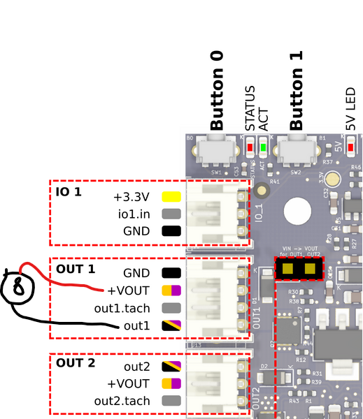
-
@beano that looks correct.
With power off and no fan connected, please use a multimeter to measure the resistance between the out1 and GND pins on that connector, to see if the mosfet is shorted. Take readings with the multimeter leads both ways round, because the mosfet body diodes may affect the reading.
-
@dc42 Hello DC, apologies for the tardy reply. I was traveling, leaving again tomorrow morning, off to India.
Anyway, I have checked the mosfet on the out1 as you have requested, it is short to GND. ~6.5R and 4.6R, if I measure between GnD/out1 pins, swapping the Fluke’s probes around also.
I anyway ordered a spare 1LC from Aurarum here in Australia, the new one is working fine. Hopefully we can get this one sorted at some point, as it will go towards a 2nd printer, running with my spare Duet 2 Wifi controller.
Appreciate your patience and support.
Cheers,
Beano -
Please send an email to warranty@duet3d.com and CC your reseller. Include a link to this forum thread and the details of your original purchase. You'll receive a reply with a form to fill out.
-
@phaedrux Thanx, will do. Currently traveling in Delhi /India, will do so over this coming weekend when I will have free time.
Thank you for support, guys, appreciated.
Cheers,
Beano