Some tools are not showed in Web interface ..
-
Trying to attach the clay extruder with dual motors but cant see it!
Dear folks ! Anyone can see the problem?I'm using Duet Expansion Breakout Board And External Drivers.
Sometime before I have already successfully used this setup with dual motors mixed extrusion. But new Resetup and version of the firmware making confuse.; Configuration file for Duet WiFi (firmware version 3.3) ; executed by the firmware on start-up ; ; generated by RepRapFirmware Configuration Tool v3.3.10 on Thu May 05 2022 09:25:32 GMT+0300 (Israel Daylight Time) ; General preferences M575 P1 S1 B57600 ; enable support for PanelDue G90 ; send absolute coordinates... M83 ; ...but relative extruder moves M550 P"Maker 1 Hybrid" ; set printer name ;M453 ; CNC Mode ;M452 C"duex.pwm5" R255 F200 ; Enable Laser mode, on exp.heater3, with max intensity being 255, and a PWM frequency of 200 ; Network M551 ** ; set password M552 S1 ; enable network M586 P0 S1 ; enable HTTP M586 P1 S0 ; disable FTP M586 P2 S0 ; disable Telnet ; Drives M569 P0 S0 ; physical drive 0 goes backwards M569 P1 S1 ; physical drive 1 goes forwards M569 P2 S1 ; physical drive 2 goes forwards M569 P3 S1 ; physical drive 3 goes forwards M569 P4 R-1 ; burn burn burn M569 P5 R1 T2.5:2.5:5:0 S1 ; physical drive 5 goes backwards --- Z MOTOR M569 P6 R1 T2.5:2.5:5:0 S1 ; physical drive 6 goes forwards ---- Y MOTOR M569 P7 R1 T2.5:2.5:5:0 S1 ; physical drive 6 goes forwards ---- Y MOTOR M569 P8 R1 T2.5:2.5:5:0 S1 M584 X0 Y6:7 Z5 U1 E3:2:8 ; set drive mapping M350 X128 Y16 Z16 U128 E16:16:16 I1 ; configure microstepping with interpolation M92 X640.00 Y171.00 Z5050.00 U640 E220:400:80 ; set steps per mm M566 X2000.00 Y1300.00 U4000 Z60.00 E800:20000:2000 ; set maximum instantaneous speed changes (mm/min) M203 X4000.00 Y4000.00 U21000 Z300.00 E1000:1800:22000 ; set maximum speeds (mm/min) M201 X600.00 Y600.00 U4500 Z80.00 E400:10000:1500 ; set accelerations (mm/s^2) M906 X1300 Y1200 Z700 U1200 E760:1000:900 I30 ; set motor currents (mA) and motor idle factor in per cent M84 S30 ; Set idle timeout ; Axis Limits M208 X0 Y0 Z0 S1 ; set axis minima M208 X700 Y600 Z500 S0 ; set axis maxima ; Endstops M574 X1 S1 P"xstop" ; configure switch-type (e.g. microswitch) endstop for low end on X via pin xstop M574 Y1 S1 P"ystop" ; configure switch-type (e.g. microswitch) endstop for low end on Y via pin ystop ; Z-Probe M558 P0 H5 F120 T6000 ; disable Z probe but set dive height, probe speed and travel speed M557 X15:215 Y15:195 S20 ; define mesh grid ; Heaters M140 H-1 ; disable heated bed (overrides default heater mapping) M308 S0 P"e0temp" Y"thermistor" T100000 B3950 ; configure sensor 0 as thermistor on pin e0temp M950 H1 C"e0heat" T0 ; create nozzle heater output on e0heat and map it to sensor 0 M307 H1 B0 S1.00 ; disable bang-bang mode for heater and set PWM limit M143 H1 S250 ; set temperature limit for heater 0 to 250C M308 S2 P"e0temp2" Y"thermistor" T100000 B3950 ; configure sensor 0 as thermistor on pin e0temp M950 H2 C"e0heat" T0 ; create nozzle heater output on e0heat and map it to sensor 0 M307 H2 B0 S1.00 ; disable bang-bang mode for heater and set PWM limit M143 H1 S120 ; set temperature limit for heater 0 to 250C ; Fans M950 F0 C"fan0" Q500 ; create fan 0 on pin fan0 and set its frequency M106 P0 S0 H-1 ; set fan 0 value. Thermostatic control is turned off M950 F1 C"fan1" Q500 ; create fan 1 on pin fan1 and set its frequency M106 P1 S1 H0 T45 ; set fan 1 value. Thermostatic control is turned on ; Tools ; Tools M563 P0 S"Plastic" D2 H0 F0 ; define tool 0 G10 P0 X0 Y0 Z0 ; set tool 0 axis offsets G10 P0 R0 S0 ; set initial tool 0 active and standby temperatures to 0C M563 P1 S"Clay" D8 H1 F3 ; define tool 2 G10 P1 X0 Y0 Z0 ; set tool 2 axis offsets G10 P1 R0 S0 ; set initial tool 2 active and standby temperatures to 0C ;M568 P1 S1 ; enable mixing for tool 2 ;M567 P1 E0.5:0.5 M563 P2 S"Spindle" ; define tool 1 G10 P2 X0 Y0 Z0 ; set tool 1 axis offsets G10 P2 R0 S0 ; set initial tool 1 active and standby temperatures to 0C ; Custom settings are not defined ; Miscellaneous M501 ; load saved parameters from non-volatile memory M911 S10 R11 P"M913 X0 Y0 G91 M83 G1 Z3 E-5 F1000" ; set voltage thresholds and actions to run on power loss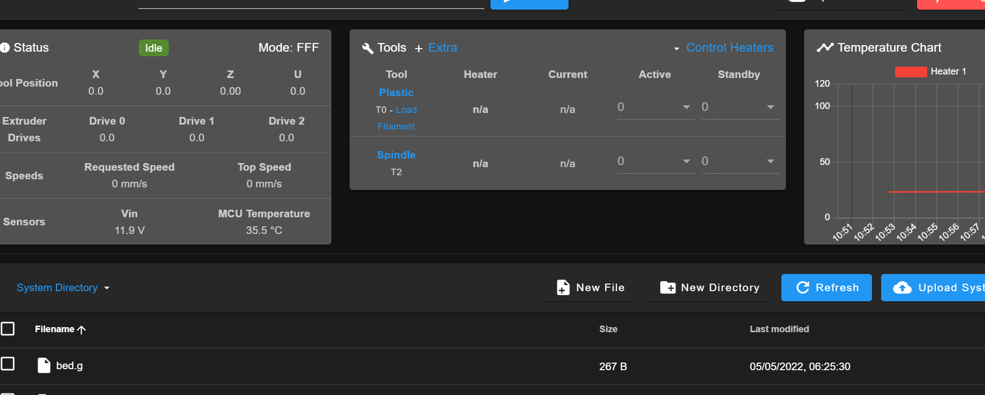 

I'll appreciate any help! Have tried so many combinations already , but no solution yet . .
-
@allsirius said in Some tools are not showed in Web interface ..:
M563 P1 S"Clay" D8 H1 F3
the driver number is the extruder driver that starts sequentially from 0 it is not the driver number
So D8 should actually be D2. This also means D2 on your plastic tool should actually be D0You also call heater 1 for the clay tool and heater 0 for the plastic tool but theres no heater 0 so I assumed the plastic tool should be H0 not H1.
And you call F3 for the clay tool but don't have an F3 definedOwns various duet boards and is the main wiki maintainer for the Teamgloomy LPC/STM32 port of RRF. Assume I'm running whatever the latest beta/stable build is
-
@jay_s_uk
Yeah, a messed up with heater , by giving a many trying attempts to see any different after all combinations with drivers %) Now I realised that made some mess. .I'll back to the first configuration ,I guess the heaters aren't a problem .
And thanks allot for quick replay , I have a feeling it will solve it.. D8 is stone of all the problems)) !
Hope I'll be back soon with the working config!
Thanks a lot Jay! -
@jay_s_uk Thanks again! it's alive!
")
If somebody will stuck with same kind of problem here is Config:
; Configuration file for Duet WiFi (firmware version 3.3)
; executed by the firmware on start-up
;
; generated by RepRapFirmware Configuration Tool v3.3.10 on Thu May 05 2022 09:25:32 GMT+0300 (Israel Daylight Time)

; General preferences
M575 P1 S1 B57600                                               ; enable support for PanelDue
G90                                                             ; send absolute coordinates...
M83                                                             ; ...but relative extruder moves
M550 P"Maker 1 Hybrid"                                          ; set printer name

;M453         			 ; CNC Mode
;M452 C"duex.pwm5" R255 F200         ; Enable Laser mode, on exp.heater3, with max intensity being 255, and a PWM frequency of 200


; Network
M551 P"******"                                                ; set password
M552 S1                                                         ; enable network
M586 P0 S1                                                      ; enable HTTP
M586 P1 S0                                                      ; disable FTP
M586 P2 S0                                                      ; disable Telnet

; Drives
M569 P0 S0                                                      ; physical drive 0 goes backwards
M569 P1 S1                                                      ; physical drive 1 goes forwards
M569 P2 S1                                                      ; physical drive 2 goes forwards
M569 P3 S1                                                      ; physical drive 3 goes forwards
M569 P4 R-1                                                     ; burn burn burn
M569 P5 R1 T2.5:2.5:5:0 S1                                      ; physical drive 5 goes backwards --- Z MOTOR
M569 P6 R1 T2.5:2.5:5:0 S1                                   ; physical drive 6 goes forwards ---- Y MOTOR
M569 P7 R1 T2.5:2.5:5:0 S1                                   ; physical drive 6 goes forwards ---- Y MOTOR
M569 P8 R1 T2.5:2.5:5:0 S1

M584 X0 Y6:7 Z5 U1 E3:8:2   ; set drive mapping
M350 X128 Y16 Z16 U128 E16 I1                                ; configure microstepping with interpolation
M92 X640.00 Y171.00 Z5050.00 U640 E220:400:80            ; set steps per mm
M566 X2000.00 Y1300.00 U4000 Z60.00 E800:20000:2000              ; set maximum instantaneous speed changes (mm/min)
M203 X4000.00 Y4000.00 U21000 Z300.00 E1000:1800:22000        ; set maximum speeds (mm/min)
M201 X600.00 Y600.00 U4500 Z80.00 E400:10000:1500        ; set accelerations (mm/s^2)
M906 X1300 Y1200 Z700 U1200 E760:1000:900  I30                     ; set motor currents (mA) and motor idle factor in per cent
M84 S30                                                         ; Set idle timeout

; Axis Limits
M208 X0 Y0 Z0 S1                                                ; set axis minima
M208 X700 Y600 Z500 S0                                          ; set axis maxima

; Endstops
M574 X1 S1 P"xstop"                                             ; configure switch-type (e.g. microswitch) endstop for low end on X via pin xstop
M574 Y1 S1 P"ystop"                                             ; configure switch-type (e.g. microswitch) endstop for low end on Y via pin ystop

; Z-Probe
M558 P0 H5 F120 T6000                                           ; disable Z probe but set dive height, probe speed and travel speed
M557 X15:215 Y15:195 S20                                        ; define mesh grid

; Heaters
M140 H-1                                                        ; disable heated bed (overrides default heater mapping)
M308 S0 P"e0temp" Y"thermistor" T100000 B4138                   ; configure sensor 0 as thermistor on pin e0temp
M950 H0 C"e0heat" T0                                            ; create nozzle heater output on e0heat and map it to sensor 0
M307 H0 B0 S1.00                                                ; disable bang-bang mode for heater  and set PWM limit
M143 H0 S250                                                 ; set temperature limit for heater 0 to 250C

M308 S1 P"e1temp" Y"thermistor" T100000 B4138                   ; configure sensor 0 as thermistor on pin e0temp
M950 H1 C"e1heat" T1                                            ; create nozzle heater output on e0heat and map it to sensor 0
M307 H1 B0 S1.00                                                ; disable bang-bang mode for heater  and set PWM limit
M143 H1 S250                                                   ; set temperature limit for heater 0 to 250C


; Fans
M950 F0 C"fan0" Q500                                            ; create fan 0 on pin fan0 and set its frequency
M106 P0 S0 H-1                                                  ; set fan 0 value. Thermostatic control is turned off
M950 F1 C"fan1" Q500                                            ; create fan 1 on pin fan1 and set its frequency
M106 P1 S1 H0 T45                                                ; set fan 1 value. Thermostatic control is turned on

; Tools


; Tools
M563 P0 S"Plastic" D0 H0 F0                                     ; define tool 0
G10 P0 X0 Y0 Z0                                                 ; set tool 0 axis offsets
G10 P0 R0 S0                                                    ; set initial tool 0 active and standby temperatures to 0C

M563 P1 S"Clay" D2:1                                             ; define tool 2
G10 P1 X0 Y0 Z0                                                 ; set tool 2 axis offsets
G10 P1 R0 S0                                                    ; set initial tool 2 active and standby temperatures to 0C
M568 P1 S1                                                      ; enable mixing for tool 2
M567 P1 E0.5:0.5

M563 P2 S"Spindle"                                            ; define tool 1
G10 P2 X0 Y0 Z0                                                 ; set tool 1 axis offsets
G10 P2 R0 S0                                                    ; set initial tool 1 active and standby temperatures to 0C

; Custom settings are not defined

; Miscellaneous
M501                                                            ; load saved parameters from non-volatile memory
M911 S10 R11 P"M913 X0 Y0 G91 M83 G1 Z3 E-5 F1000"              ; set voltage thresholds and actions to run on power loss
P.s. Still have some work to do with Laser and Spindle , but this story for another chapter .. ::)
The Mixed 2motor extruder for clay are working! Cheers!")
-
@allsirius said in Some tools are not showed in Web interface ..:
@jay_s_uk Thanks again! it's alive!
If somebody will stuck with same kind of problem here is Config:
; Configuration file for Duet WiFi (firmware version 3.3)
; executed by the firmware on start-up
;
; generated by RepRapFirmware Configuration Tool v3.3.10 on Thu May 05 2022 09:25:32 GMT+0300 (Israel Daylight Time)

; General preferences
M575 P1 S1 B57600                                               ; enable support for PanelDue
G90                                                             ; send absolute coordinates...
M83                                                             ; ...but relative extruder moves
M550 P"Maker 1 Hybrid"                                          ; set printer name

;M453         			 ; CNC Mode
;M452 C"duex.pwm5" R255 F200         ; Enable Laser mode, on exp.heater3, with max intensity being 255, and a PWM frequency of 200


; Network
M551 P"******"                                                ; set password
M552 S1                                                         ; enable network
M586 P0 S1                                                      ; enable HTTP
M586 P1 S0                                                      ; disable FTP
M586 P2 S0                                                      ; disable Telnet

; Drives
M569 P0 S0                                                      ; physical drive 0 goes backwards
M569 P1 S1                                                      ; physical drive 1 goes forwards
M569 P2 S1                                                      ; physical drive 2 goes forwards
M569 P3 S1                                                      ; physical drive 3 goes forwards
M569 P4 R-1                                                     ; burn burn burn
M569 P5 R1 T2.5:2.5:5:0 S1                                      ; physical drive 5 goes backwards --- Z MOTOR
M569 P6 R1 T2.5:2.5:5:0 S1                                   ; physical drive 6 goes forwards ---- Y MOTOR
M569 P7 R1 T2.5:2.5:5:0 S1                                   ; physical drive 6 goes forwards ---- Y MOTOR
M569 P8 R1 T2.5:2.5:5:0 S1

M584 X0 Y6:7 Z5 U1 E3:8:2   ; set drive mapping
M350 X128 Y16 Z16 U128 E16 I1                                ; configure microstepping with interpolation
M92 X640.00 Y171.00 Z5050.00 U640 E220:400:80            ; set steps per mm
M566 X2000.00 Y1300.00 U4000 Z60.00 E800:20000:2000              ; set maximum instantaneous speed changes (mm/min)
M203 X4000.00 Y4000.00 U21000 Z300.00 E1000:1800:22000        ; set maximum speeds (mm/min)
M201 X600.00 Y600.00 U4500 Z80.00 E400:10000:1500        ; set accelerations (mm/s^2)
M906 X1300 Y1200 Z700 U1200 E760:1000:900  I30                     ; set motor currents (mA) and motor idle factor in per cent
M84 S30                                                         ; Set idle timeout

; Axis Limits
M208 X0 Y0 Z0 S1                                                ; set axis minima
M208 X700 Y600 Z500 S0                                          ; set axis maxima

; Endstops
M574 X1 S1 P"xstop"                                             ; configure switch-type (e.g. microswitch) endstop for low end on X via pin xstop
M574 Y1 S1 P"ystop"                                             ; configure switch-type (e.g. microswitch) endstop for low end on Y via pin ystop

; Z-Probe
M558 P0 H5 F120 T6000                                           ; disable Z probe but set dive height, probe speed and travel speed
M557 X15:215 Y15:195 S20                                        ; define mesh grid

; Heaters
M140 H-1                                                        ; disable heated bed (overrides default heater mapping)
M308 S0 P"e0temp" Y"thermistor" T100000 B4138                   ; configure sensor 0 as thermistor on pin e0temp
M950 H0 C"e0heat" T0                                            ; create nozzle heater output on e0heat and map it to sensor 0
M307 H0 B0 S1.00                                                ; disable bang-bang mode for heater  and set PWM limit
M143 H0 S250                                                 ; set temperature limit for heater 0 to 250C

M308 S1 P"e1temp" Y"thermistor" T100000 B4138                   ; configure sensor 0 as thermistor on pin e0temp
M950 H1 C"e1heat" T1                                            ; create nozzle heater output on e0heat and map it to sensor 0
M307 H1 B0 S1.00                                                ; disable bang-bang mode for heater  and set PWM limit
M143 H1 S250                                                   ; set temperature limit for heater 0 to 250C


; Fans
M950 F0 C"fan0" Q500                                            ; create fan 0 on pin fan0 and set its frequency
M106 P0 S0 H-1                                                  ; set fan 0 value. Thermostatic control is turned off
M950 F1 C"fan1" Q500                                            ; create fan 1 on pin fan1 and set its frequency
M106 P1 S1 H0 T45                                                ; set fan 1 value. Thermostatic control is turned on

; Tools


; Tools
M563 P0 S"Plastic" D0 H0 F0                                     ; define tool 0
G10 P0 X0 Y0 Z0                                                 ; set tool 0 axis offsets
G10 P0 R0 S0                                                    ; set initial tool 0 active and standby temperatures to 0C

M563 P1 S"Clay" D2:1                                             ; define tool 2
G10 P1 X0 Y0 Z0                                                 ; set tool 2 axis offsets
G10 P1 R0 S0                                                    ; set initial tool 2 active and standby temperatures to 0C
M568 P1 S1                                                      ; enable mixing for tool 2
M567 P1 E0.5:0.5

M563 P2 S"Spindle"                                            ; define tool 1
G10 P2 X0 Y0 Z0                                                 ; set tool 1 axis offsets
G10 P2 R0 S0                                                    ; set initial tool 1 active and standby temperatures to 0C

; Custom settings are not defined

; Miscellaneous
M501                                                            ; load saved parameters from non-volatile memory
M911 S10 R11 P"M913 X0 Y0 G91 M83 G1 Z3 E-5 F1000"              ; set voltage thresholds and actions to run on power loss
P.s. Still have some work to do with Laser and Spindle , but this story for another chapter .. ::)
The Mixed 2motor extruder for clay are working! Cheers!BTW. if I use command M542 ; Enable Laser mode - it switching the DWC to CNC mode and there are no tools are showed at all.. But I'll back to it later !
-
@allsirius yes, thats pretty normal to switch to the CNC interface when in Laser mode as its then down to the gcode to control the laser using M3 (for on), M5 (for off) and then the S value in each G0/G1 move to control the laser power