auto bed leveling
-
@matej1006 I suppose the question is, whats offset from what? is the bltouch attached to the tool carrier and everything tool is offset from it?
the easiest way is probably with a tool unmounted, go to 0,0 and then measure everything in relation to that -
@jay_s_uk
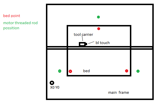
fast scheme what i haveand now my bl touch have off set just on x axis.
so i insert point of bed point coordinate when will be my bl touch in the middle of bolt for each of three bed points -
@matej1006 said in auto bed leveling:
Hello,
i would like to know which coordinate i must insert to define where in my threaded rod for each of my 3 motor for z axis.
do i need to set form center of my bl touch or center of the nozzle or which?
i do have toolchange system.
Greatings Matej
The XY coordinates are all referenced to X=0 Y=0.
Frederick
-
@fcwilt yeah i use which center? carrier center point or BL touch center for define x and y coordinate
-
@matej1006 said in auto bed leveling:
@fcwilt yeah i use which center? carrier center point or BL touch center for define x and y coordinate
X=0 Y=0 is a fixed point on your machine, usually.
For example, if you have an X axis that runs from -150 to 150 and Y from 0 to 200 then you know where X=0 Y=0 is.
Frederick
-
@fcwilt yeah hehe
what center do i use when i will be above the screw in bed.
is that center of bl touch or carrier
-
@matej1006 said in auto bed leveling:
@fcwilt yeah hehe
what center do i use when i will be above the screw in bed.
is that center of bl touch or carrier
It has nothing to do with the center of anything. It has to do where the point X=0 Y=0 is located. That is determined by the min/max settings of the X and Y axes. If the min/max settings of the axes do not change the X=0 Y=0 point is always in a fixed location.
It is not related to the "carrier" or the "Z probe", only to the X and Y axes.
Frederick
-
@fcwilt so then is the best to define out of 3d printer model where is each screw ?
-
@matej1006 said in auto bed leveling:
@fcwilt so then is the best to define out of 3d printer model where is each screw ?
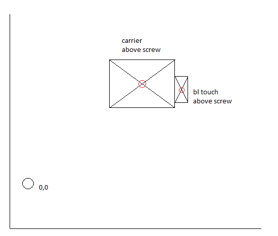
Maybe this will help:

The green bar is the Y axis.
The red bar is the X axis.
The gray squares are the stepper motors. The distances show where they are in relation to the X and Y axes.
The text below each gray square is the coordinates of the stepper in relation to X=0 Y=0.
Make sense?
Frederick
-
@fcwilt
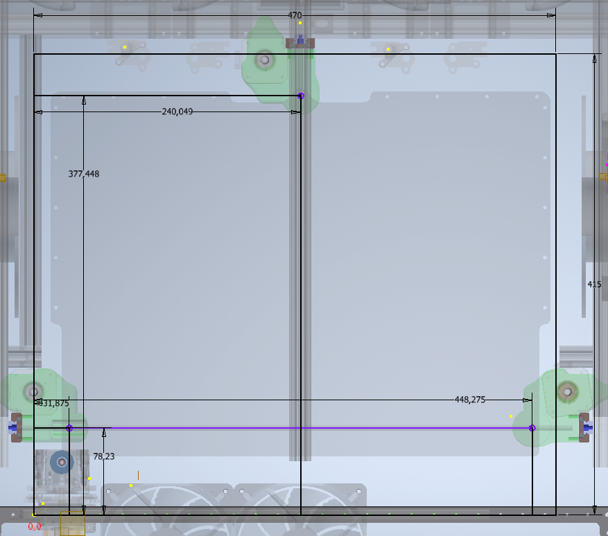
this is what i was able to get out it's this OK -
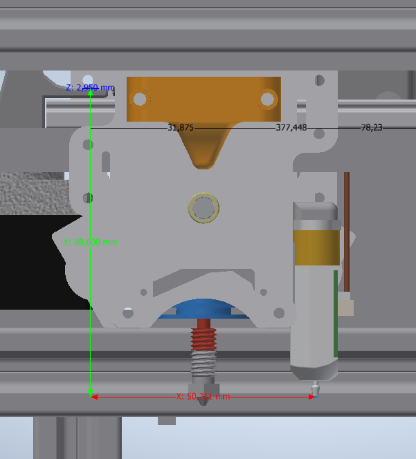
distance from bl touch from x0 y0 so i won't be able to probe right on the screw -
@matej1006 said in auto bed leveling:
distance from bl touch from x0 y0 so i won't be able to probe right on the screwYou don't need to be able to do that. Just get as close as you can.
When the firmware knows the locations where the bed is being lifted and where it is being probed it can do the math and get it all to work out.
This is the relevant information from my printer:
M671 X-180:0:180 Y-65:130:-65 S3 ; positions of ball studs

 ; --- probe near ball studs ---

G30 P0 X-145 Y-65 Z-99999    ; probe near ball stud #1
G30 P1 X0    Y100 Z-99999    ; probe near ball stud #2
G30 P2 X145  Y-65 Z-99999 S3 ; probe near ball stud #3
Frederick