Problems with Duet 3 Mini 5+ WiFi
-
@unforgivenll said in Problems with Duet 3 Mini 5+ WiFi:
@fcwilt My Y min is actually at the back of my bed. I don't know if that makes a difference. I think I know where this is placed in config.g but I have no idea where it is placed in bed.g. The E1 is a typo, I'm on my phone and was copy/pasting.
So it should be ?
M584 X0.0 Y0.1 Z0.2:0.3 E121.0
M671 X-25:335 Y155:155 S0.5 ; leadscrews at left (connected to Z) and rightG28 ; home
G30 P0 X25 Y155 Z-99999 ; probe near a leadscrew, half way along Y axis
G30 P1 X285 Y155 Z-99999 S2 ; probe near a leadscrew and calibrate 2 motorsIF your leadscrews line up with the probe when the probe is at Y=155 then then your M671 and G30s are good.
Frederick
-
-
@unforgivenll said in Problems with Duet 3 Mini 5+ WiFi:
@fcwilt Thank you. I asked where to put the new bed config info because there is some there already. Do I keep what's there or do I replace it with the new config?
I like to keep related things together.
So my bed.g file has all the commands needed to level the bed.
Some of the commands in my bed.g are often put in config.g but I don't do that.
The M584 should stay in config.g since it is fundamental to the printer working.
The M671, G28 and the G30s, can all go into bed.g
There should be no G28s or G30s in config.g ever.
And if there is a M671 in config.g, remove it and rely on the one in bed.g
Frederick
-
@fcwilt Thank you. Here's my configs again if you want to look at them. I'm working on sensor less homing and setting my Bltouch height from the bed next. It will probably be awhile before you hear from me again as I have to wait for some parts to proceed. I'm sure you won't mind the peace. I appreciate everything.
-
@unforgivenll said in Problems with Duet 3 Mini 5+ WiFi:
@fcwilt Thank you. Here's my configs again if you want to look at them. I'm working on sensor less homing and setting my Bltouch height from the bed next. It will probably be awhile before you hear from me again as I have to wait for some parts to proceed. I'm sure you won't mind the peace. I appreciate everything.
In the future if you would copy-and-paste the contents of files using the </> it makes it easier on responders. They don't need to download a file to view.
Each </> tag creates a scrollable region right within your post, as you can see below.
; Configuration file for Duet 3 Mini 5+ (firmware version 3.3)
; executed by the firmware on start-up
;
; generated by RepRapFirmware Configuration Tool v3.3.10 on Wed Jun 22 2022 17:05:21 GMT-0400 (Eastern Daylight Time)

; General preferences
M575 P1 S1 B57600                                            ; enable support for PanelDue
G90                                                          ; send absolute coordinates...
M83                                                          ; ...but relative extruder moves
M550 P"SLR3DP"                                               ; set printer name

; Wait a moment for the CAN expansion boards to start
G4 S2

; Network
M551 P"554306"                                               ; set password
M552 S1                                                      ; enable network
M586 P0 S1                                                   ; enable HTTP
M586 P1 S0                                                   ; disable FTP
M586 P2 S0                                                   ; disable Telnet

; Drives
M569 P0.0 S1                                                 ; physical drive 0.0 goes forwards
M569 P0.1 S1                                                 ; physical drive 0.1 goes forwards
M569 P0.2 S1                                                 ; physical drive 0.2 goes forwards
M569 P121.0 S1                                               ; physical drive 121.0 goes forwards
M584 X0.0 Y0.1 Z0.2:0.3 E121.0                               ; set drive mapping
M350 X16 Y16 Z16 E16 I1                                      ; configure microstepping with interpolation
M92 X80.00 Y80.00 Z400.00 E420.00                            ; set steps per mm
M566 X900.00 Y900.00 Z60.00 E120.00                          ; set maximum instantaneous speed changes (mm/min)
M203 X6000.00 Y6000.00 Z180.00 E1200.00                      ; set maximum speeds (mm/min)
M201 X500.00 Y500.00 Z20.00 E250.00                          ; set accelerations (mm/s^2)
M906 X850 Y850 Z850 E390 I30                                 ; set motor currents (mA) and motor idle factor in per cent
M84 S30                                                      ; Set idle timeout

; Axis Limits
M208 X0 Y0 Z0 S1                                             ; set axis minima
M208 X310 Y370 Z400 S0                                       ; set axis maxima

; Endstops
M574 X1 S3                                                   ; configure sensorless endstop for low end on X
M574 Y1 S3                                                   ; configure sensorless endstop for low end on Y
M574 Z1 S2                                                   ; configure Z-probe endstop for low end on Z

; Z-Probe
M950 S0 C"121.io0.out"                                       ; create servo pin 0 for BLTouch
M558 P9 C"121.io0.in" H5 F120 T6000                          ; set Z probe type to bltouch and the dive height + speeds
G31 P500 X50 Y-55 Z2.5                                       ; set Z probe trigger value, offset and trigger height
M557 X15:215 Y15:195 S20                                     ; define mesh grid

; Heaters
M308 S0 P"temp0" Y"thermistor" T100000 B4138                 ; configure sensor 0 as thermistor on pin temp0
M950 H0 C"out0" T0                                           ; create bed heater output on out0 and map it to sensor 0
M307 H0 B1 S1.00                                             ; enable bang-bang mode for the bed heater and set PWM limit
M140 H0                                                      ; map heated bed to heater 0
M143 H0 S120                                                 ; set temperature limit for heater 0 to 120C
M308 S1 P"121.temp0" Y"thermistor" T500000 B4723 C1.19622e-7 ; configure sensor 1 as thermistor on pin 121.temp0
M950 H1 C"121.out0" T1                                       ; create nozzle heater output on 121.out0 and map it to sensor 1
M307 H1 B0 S1.00                                             ; disable bang-bang mode for heater  and set PWM limit
M143 H1 S280                                                 ; set temperature limit for heater 1 to 280C

; Fans
M950 F0 C"121.out1" Q500                                     ; create fan 0 on pin 121.out1 and set its frequency
M106 P0 S0 H-1                                               ; set fan 0 value. Thermostatic control is turned off
M950 F1 C"121.out2" Q500                                     ; create fan 1 on pin 121.out2 and set its frequency
M106 P1 S1 H1 T45                                            ; set fan 1 value. Thermostatic control is turned on

; Tools
M563 P0 D0 H1 F0                                             ; define tool 0
G10 P0 X0 Y0 Z0                                              ; set tool 0 axis offsets
G10 P0 R0 S0                                                 ; set initial tool 0 active and standby temperatures to 0C

; Custom settings are not defined
; bed.g ; called to perform automatic bed compensation via G32 ; ; generated by RepRapFirmware Configuration Tool v3.3.10 on Wed Jun 22 2022 17:05:21 GMT-0400 (Eastern Daylight Time) M561 ; clear any bed transform G29 ; probe the bed and enable compensation M671 X-25:335 Y155:155 S0.5 ; leadscrews at left (connected to Z) and right G28 ; home G30 P0 X25 Y155 Z-99999 ; probe near a leadscrew, half way along Y axis G30 P1 X285 Y155 Z-99999 S2 ; probe near a leadscrew and calibrate 2 motorsNow as to your bed.g file:
You have a G29 which some folks do include but bed.g is really meant to handle bed leveling. G29 is related to Mesh Bed Compensation - something else entirely.
G30 executes bed.g and should level the bed.
G29 executes mesh.g, if found, and it should create the height map needed for Mesh Bed Compensation.
And creating the height map should only happen after leveling the bed. Also prior to creating or loading a height map you need to set the Z=0 Datum using a single G30 at your chosen reference point. Many folks use the first point of the height map mesh, some folks (like me) use the center of the bed.
As I mentioned I like to keep related things together so my mesh.g file has only the commands needed to create the height map.
Frederick
-
@fcwilt I'm sorry I didn't realize that. I also realized for some reason I had 155 stuck in my head for Y center, when it was x center. I changed it to 185. I didn't have a mesh.g so I created one and added the G29 there. All the commands were added by the auto config. It was far as I had gotten before I started changing it with you.
; bed.g
; called to perform automatic bed compensation via G32
;
; generated by RepRapFirmware Configuration Tool v3.3.10 on Wed Jun 22 2022 17:05:21 GMT-0400 (Eastern Daylight Time)
M561 ; clear any bed transform
M671 X-25:335 Y185:185 S0.5 ; leadscrews at left (connected to Z) and right
G28 ; home
G30 P0 X25 Y185 Z-99999 ; probe near a leadscrew, half way along Y axis
G30 P1 X285 Y185 Z-99999 S2 ; probe near a leadscrew and calibrate 2 motors
; Configuration file for Duet 3 Mini 5+ (firmware version 3.3) ; executed by the firmware on start-up ; ; generated by RepRapFirmware Configuration Tool v3.3.10 on Wed Jun 22 2022 17:05:21 GMT-0400 (Eastern Daylight Time) ; General preferences M575 P1 S1 B57600 ; enable support for PanelDue G90 ; send absolute coordinates... M83 ; ...but relative extruder moves M550 P"SLR3DP" ; set printer name ; Wait a moment for the CAN expansion boards to start G4 S2 ; Network M551 P"554306" ; set password M552 S1 ; enable network M586 P0 S1 ; enable HTTP M586 P1 S0 ; disable FTP M586 P2 S0 ; disable Telnet ; Drives M569 P0.0 S1 ; physical drive 0.0 goes forwards M569 P0.1 S1 ; physical drive 0.1 goes forwards M569 P0.2 S1 ; physical drive 0.2 goes forwards M569 P121.0 S1 ; physical drive 121.0 goes forwards M584 X0.0 Y0.1 Z0.2:0.3 E121.0 ; set drive mapping M350 X16 Y16 Z16 E16 I1 ; configure microstepping with interpolation M92 X80.00 Y80.00 Z400.00 E420.00 ; set steps per mm M566 X900.00 Y900.00 Z60.00 E120.00 ; set maximum instantaneous speed changes (mm/min) M203 X6000.00 Y6000.00 Z180.00 E1200.00 ; set maximum speeds (mm/min) M201 X500.00 Y500.00 Z20.00 E250.00 ; set accelerations (mm/s^2) M906 X850 Y850 Z850 E390 I30 ; set motor currents (mA) and motor idle factor in per cent M84 S30 ; Set idle timeout ; Axis Limits M208 X0 Y0 Z0 S1 ; set axis minima M208 X310 Y370 Z400 S0 ; set axis maxima ; Endstops M574 X1 S3 ; configure sensorless endstop for low end on X M574 Y1 S3 ; configure sensorless endstop for low end on Y M574 Z1 S2 ; configure Z-probe endstop for low end on Z ; Z-Probe M950 S0 C"121.io0.out" ; create servo pin 0 for BLTouch M558 P9 C"121.io0.in" H5 F120 T6000 ; set Z probe type to bltouch and the dive height + speeds G31 P500 X50 Y-55 Z2.5 ; set Z probe trigger value, offset and trigger height M557 X15:215 Y15:195 S20 ; define mesh grid ; Heaters M308 S0 P"temp0" Y"thermistor" T100000 B4138 ; configure sensor 0 as thermistor on pin temp0 M950 H0 C"out0" T0 ; create bed heater output on out0 and map it to sensor 0 M307 H0 B1 S1.00 ; enable bang-bang mode for the bed heater and set PWM limit M140 H0 ; map heated bed to heater 0 M143 H0 S120 ; set temperature limit for heater 0 to 120C M308 S1 P"121.temp0" Y"thermistor" T500000 B4723 C1.19622e-7 ; configure sensor 1 as thermistor on pin 121.temp0 M950 H1 C"121.out0" T1 ; create nozzle heater output on 121.out0 and map it to sensor 1 M307 H1 B0 S1.00 ; disable bang-bang mode for heater and set PWM limit M143 H1 S280 ; set temperature limit for heater 1 to 280C ; Fans M950 F0 C"121.out1" Q500 ; create fan 0 on pin 121.out1 and set its frequency M106 P0 S0 H-1 ; set fan 0 value. Thermostatic control is turned off M950 F1 C"121.out2" Q500 ; create fan 1 on pin 121.out2 and set its frequency M106 P1 S1 H1 T45 ; set fan 1 value. Thermostatic control is turned on ; Tools M563 P0 D0 H1 F0 ; define tool 0 G10 P0 X0 Y0 Z0 ; set tool 0 axis offsets G10 P0 R0 S0 ; set initial tool 0 active and standby temperatures to 0C ; Custom settings are not definedG29 ; probe the bed and enable compensationHow's this?
-
@unforgivenll said in Problems with Duet 3 Mini 5+ WiFi:
@fcwilt I'm sorry I didn't realize that. I also realized for some reason I had 155 stuck in my head for Y center, when it was x center. I changed it to 185. I didn't have a mesh.g so I created one and added the G29 there. All the commands were added by the auto config. It was far as I had gotten before I started changing it with you.
; bed.g
; called to perform automatic bed compensation via G32
;
; generated by RepRapFirmware Configuration Tool v3.3.10 on Wed Jun 22 2022 17:05:21 GMT-0400 (Eastern Daylight Time)
M561 ; clear any bed transform
M671 X-25:335 Y185:185 S0.5 ; leadscrews at left (connected to Z) and right
G28 ; home
G30 P0 X25 Y185 Z-99999 ; probe near a leadscrew, half way along Y axis
G30 P1 X285 Y185 Z-99999 S2 ; probe near a leadscrew and calibrate 2 motors
; Configuration file for Duet 3 Mini 5+ (firmware version 3.3) ; executed by the firmware on start-up ; ; generated by RepRapFirmware Configuration Tool v3.3.10 on Wed Jun 22 2022 17:05:21 GMT-0400 (Eastern Daylight Time) ; General preferences M575 P1 S1 B57600 ; enable support for PanelDue G90 ; send absolute coordinates... M83 ; ...but relative extruder moves M550 P"SLR3DP" ; set printer name ; Wait a moment for the CAN expansion boards to start G4 S2 ; Network M551 P"554306" ; set password M552 S1 ; enable network M586 P0 S1 ; enable HTTP M586 P1 S0 ; disable FTP M586 P2 S0 ; disable Telnet ; Drives M569 P0.0 S1 ; physical drive 0.0 goes forwards M569 P0.1 S1 ; physical drive 0.1 goes forwards M569 P0.2 S1 ; physical drive 0.2 goes forwards M569 P121.0 S1 ; physical drive 121.0 goes forwards M584 X0.0 Y0.1 Z0.2:0.3 E121.0 ; set drive mapping M350 X16 Y16 Z16 E16 I1 ; configure microstepping with interpolation M92 X80.00 Y80.00 Z400.00 E420.00 ; set steps per mm M566 X900.00 Y900.00 Z60.00 E120.00 ; set maximum instantaneous speed changes (mm/min) M203 X6000.00 Y6000.00 Z180.00 E1200.00 ; set maximum speeds (mm/min) M201 X500.00 Y500.00 Z20.00 E250.00 ; set accelerations (mm/s^2) M906 X850 Y850 Z850 E390 I30 ; set motor currents (mA) and motor idle factor in per cent M84 S30 ; Set idle timeout ; Axis Limits M208 X0 Y0 Z0 S1 ; set axis minima M208 X310 Y370 Z400 S0 ; set axis maxima ; Endstops M574 X1 S3 ; configure sensorless endstop for low end on X M574 Y1 S3 ; configure sensorless endstop for low end on Y M574 Z1 S2 ; configure Z-probe endstop for low end on Z ; Z-Probe M950 S0 C"121.io0.out" ; create servo pin 0 for BLTouch M558 P9 C"121.io0.in" H5 F120 T6000 ; set Z probe type to bltouch and the dive height + speeds G31 P500 X50 Y-55 Z2.5 ; set Z probe trigger value, offset and trigger height M557 X15:215 Y15:195 S20 ; define mesh grid ; Heaters M308 S0 P"temp0" Y"thermistor" T100000 B4138 ; configure sensor 0 as thermistor on pin temp0 M950 H0 C"out0" T0 ; create bed heater output on out0 and map it to sensor 0 M307 H0 B1 S1.00 ; enable bang-bang mode for the bed heater and set PWM limit M140 H0 ; map heated bed to heater 0 M143 H0 S120 ; set temperature limit for heater 0 to 120C M308 S1 P"121.temp0" Y"thermistor" T500000 B4723 C1.19622e-7 ; configure sensor 1 as thermistor on pin 121.temp0 M950 H1 C"121.out0" T1 ; create nozzle heater output on 121.out0 and map it to sensor 1 M307 H1 B0 S1.00 ; disable bang-bang mode for heater and set PWM limit M143 H1 S280 ; set temperature limit for heater 1 to 280C ; Fans M950 F0 C"121.out1" Q500 ; create fan 0 on pin 121.out1 and set its frequency M106 P0 S0 H-1 ; set fan 0 value. Thermostatic control is turned off M950 F1 C"121.out2" Q500 ; create fan 1 on pin 121.out2 and set its frequency M106 P1 S1 H1 T45 ; set fan 1 value. Thermostatic control is turned on ; Tools M563 P0 D0 H1 F0 ; define tool 0 G10 P0 X0 Y0 Z0 ; set tool 0 axis offsets G10 P0 R0 S0 ; set initial tool 0 active and standby temperatures to 0C ; Custom settings are not definedG29 ; probe the bed and enable compensationHow's this?
Well you cannot put G29 in mesh.g because G29 executes mesh.g - so it will likely just go round and round.
You need to do something like this
G1 Xaaa Ybbb ; where aaa and bbb are for the point you have chosen for the Z=0 Datum reference point G30 ; this probes the bed and sets the Z=0 Datum M557 Xaaa:bbb Yccc:ddd Pe:f ; this sets the grid that is probed to create the height map - you need to chose values for aaa,bbb,ccc,ddd,e and f G29 S0 ; this creates the height map - notice the S0 -
@fcwilt Thank you again. I'm clearly over my head here. I thought I had a handle on this before I started. Unfortunately I have a lot of money plus time into this project, so I can't walk away from it. I'm feeling a little overwhelmed at the moment. I'm 45 and just started using 3d printers a little over a year ago. I don't have any background whatsoever in CNC, CAD, or 3D printing (maybe a tiny bit in general electronic/soldering). Anyhow, I'll try to implement your advise when the new parts come in. I'm waiting on a build plate and have yet to setup/order a custom heater. I appreciate your help, patience and time. Hopefully I can make some progress on my own when I get the new parts. I'm not feeling real confident at the moment.
-
It's really not so bad. You can get as fancy or simple as you like. And once it's setup, the hard part is done.
45 isn't old. You're probably half the age of some of the people here.
")
Read lots. Sleep on it. Try and implement it. Ask questions. We will get you there eventually.
-
@unforgivenll said in Problems with Duet 3 Mini 5+ WiFi:
@fcwilt Thank you again. I'm clearly over my head here. I thought I had a handle on this before I started. Unfortunately I have a lot of money plus time into this project, so I can't walk away from it. I'm feeling a little overwhelmed at the moment. I'm 45 and just started using 3d printers a little over a year ago. I don't have any background whatsoever in CNC, CAD, or 3D printing (maybe a tiny bit in general electronic/soldering). Anyhow, I'll try to implement your advise when the new parts come in. I'm waiting on a build plate and have yet to setup/order a custom heater. I appreciate your help, patience and time. Hopefully I can make some progress on my own when I get the new parts. I'm not feeling real confident at the moment.
I started working with 3D printing in my late 60s, I just turned 72.
Feel free to ask whatever questions you have. Someone here is likely to answer them. I check in here most every day but I don't spend too much time here, lots of other things I need to do.
Frederick
-
@fcwilt Thank you you I appreciate it. Unfortunately I do have to wait for parts. I don't think there's a lot more I can do until I have them. At least none I can think of that makes sense without the build plate or heater.
-
@unforgivenll said in Problems with Duet 3 Mini 5+ WiFi:
@fcwilt Thank you you I appreciate it. Unfortunately I do have to wait for parts. I don't think there's a lot more I can do until I have them. At least none I can think of that makes sense without the build plate or heater.
Well there are things about GCode you can learn, such as there being a short form for M208
M280 Xmin:max Ymin:max Zmin:max
All on one line instead of two.
What hardware are you using? Your config.g file mentions a Duet 3 Mini but the M584 line suggests you have an external device on the CAN bus.
Frederick
-
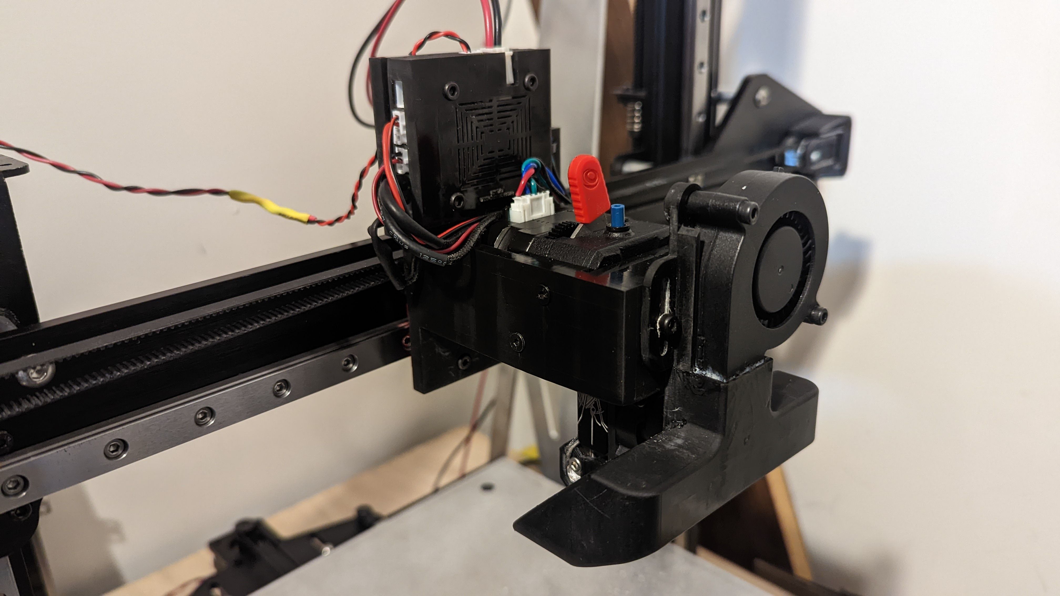
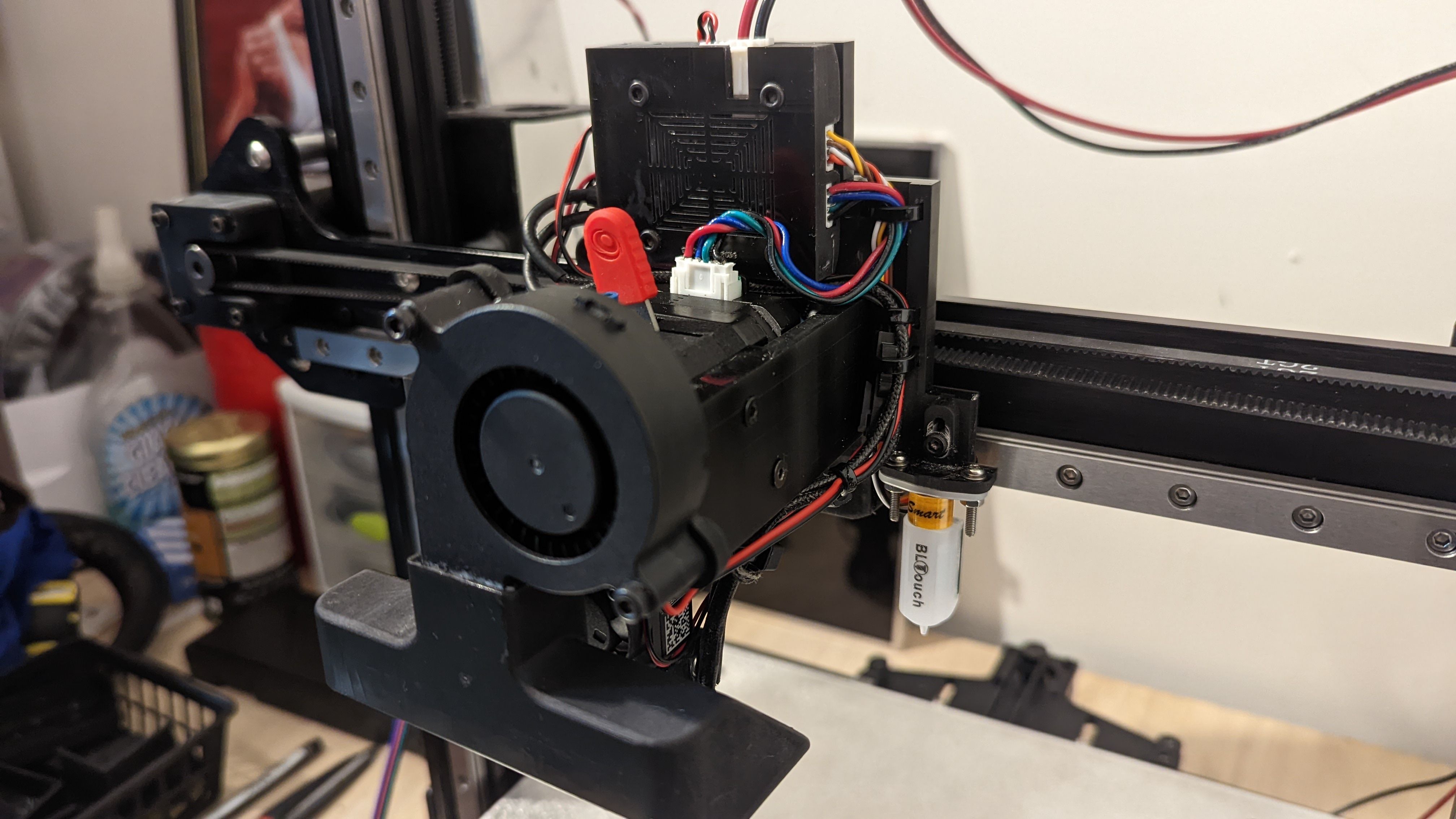
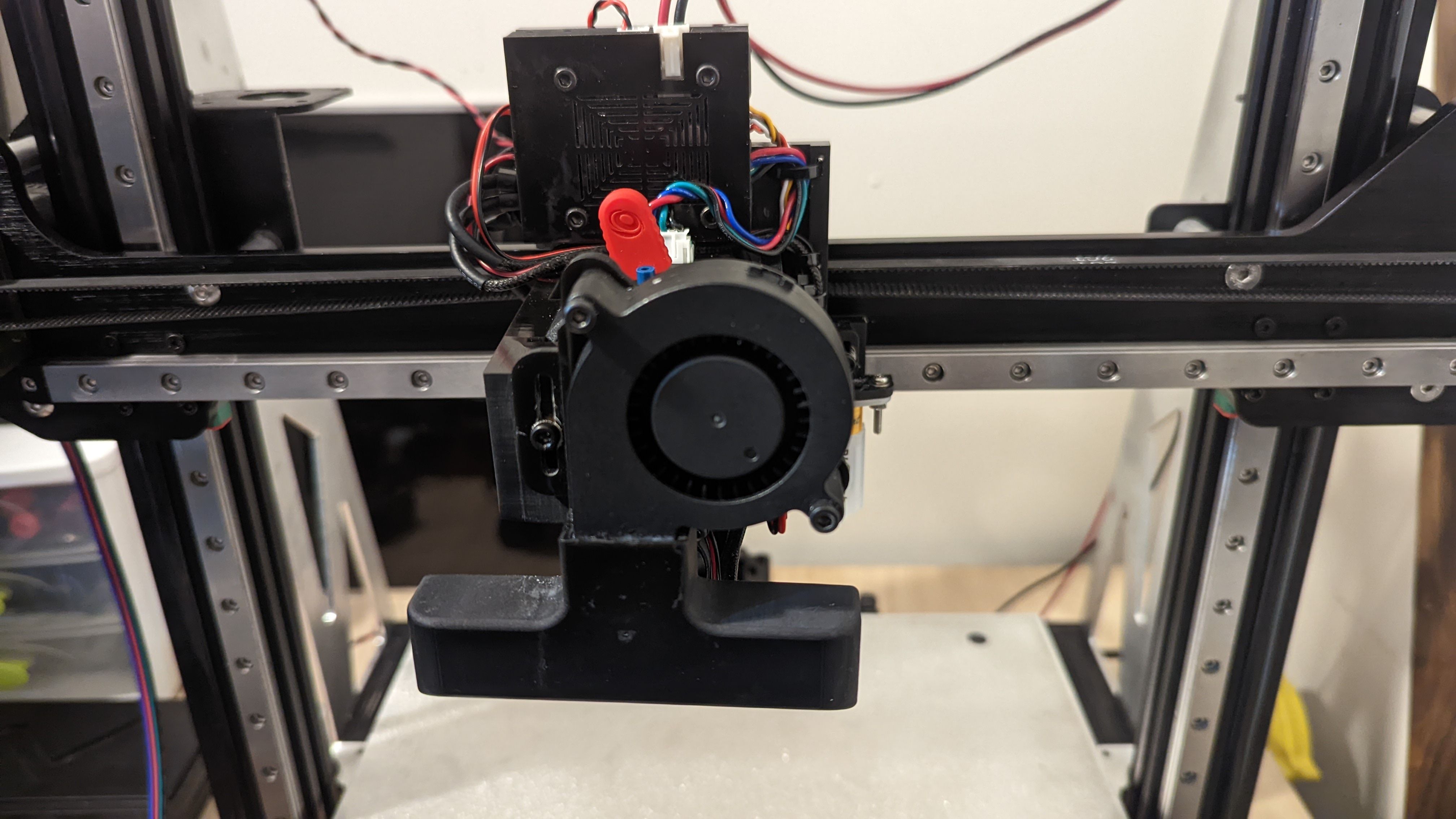
@fcwilt I have the tool board with the BLTOUCH, Lgx, mosquito magnum, part fan, cooling fan, thermistor and heater setup and working.I designed the carriage and the mount. The duct was designed by someone on Thingiverse, * just modified my carriage to work with it.
-
Is the Z-probe as close to the nozzle as you could get it?
That is a long ways away.
Frederick
-
@fcwilt I'm sure someone more experienced than me could have done a better job. Like I said I don't have any background in Cad and only starting using it less than a month ago.
-
@unforgivenll said in Problems with Duet 3 Mini 5+ WiFi:
@fcwilt I'm sure someone more experienced than me could have done a better job. Like I said I don't have any background in Cad and only starting using it less than a month ago.
Don't be surprised if you find yourself re-designing parts of your printer. I have one printer that is so different now from it's first version there is very little left of the first one.
I recently converted a printer using stall detection for homing to using actual endstop sensors. It took me several tries to get it done to my satisfaction.
For me that's part of the enjoyment. Learning from experience and striving for improvements.
Frederick
-
@fcwilt Yeah I plan to take another look at it at some point. It took me quite awhile to get that far. I figured when I was actually able to print I'd have to revise it. All I have at the moment is a resin printer. I don't trust it to last long.
-
@unforgivenll said in Problems with Duet 3 Mini 5+ WiFi:
@fcwilt Yeah I plan to take another look at it at some point. It took me quite awhile to get that far. I figured when I was actually able to print I'd have to revise it. All I have at the moment is a resin printer. I don't trust it to last long.
You are a brave pioneer. I watched a few videos regards resin printers. That was enough to keep me far away from the complexity of the entire process.
The results can be impressive and well suited to certain projects.
Frederick
-
@fcwilt Well it looks like it will be a month or so before the parts are shipped. I started this project over a year ago, another month or so isn't too bad, I guess.
-
@fcwilt It's been a long time since I was last in contact with you. I had ordered some CNC parts and they were supposed to take a month or so. Flash forward to today and I might receive them Wednesday. Since then I have changed my mind on the hotend mount I had designed as the Hero Me designer came out with a mount specifically for my setup. I am unable to print with the materials that I need so I'll have to order those as well. I just wanted to touch base. Hopefully I can have all the electrical and mechanical parts setup in the near future. I could still use your help with the software when the time comes, if you're available your help and guidance would be greatly appreciated.