2 PT100 daughterboards for the bed heaters, Code?
-
Hello,
I am currently building a relatively large 3D printer. My board is a Duet2 Wifi. Since I don't have any experience yet, I used the RRF Config Tool for the configuration. I can already address and move the axes, I can also warm up the 2 print heads, but they are displayed somewhat awkwardly in the terminal. The heating bed consists of 4 heating elements, each 400x400mm. So I have a total of 4250 watts. I have planned 2 PT100 daughterboards for this and hopefully I have connected them correctly according to the instructions (see photos)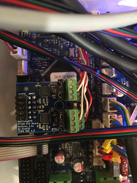 . I don't understand the description in the instructions, especially how to get the elements visible in the terminal. I am attaching the current code and some photos. The second question is how can I address the 2 extruders for the 2 print heads.
Can someone send me a code that I can just copy and paste?
best regards
Aktueller Config.g:
; Konfiguration File for Duet WiFi (firmware version 3.3)
; executed by the firmware on start-up
;
; generated by RepRapFirmware Configuration Tool v3.3.10 on Wed Jun 29 2022 17:59:36 GMT+0200 (Mitteleuropäische Sommerzeit); General preferences
G90 ; send absolute coordinates...
M83 ; ...but relative extruder moves
M550 P"axiom eins DMH" ; set printer name; Network
M552 S1 ; enable network
M586 P0 S1 ; enable HTTP
M586 P1 S0 ; disable FTP
M586 P2 S0 ; disable Telnet; Drives
M569 P0 S1 ; physical drive 0 goes forwards
M569 P1 S1 ; physical drive 1 goes forwards
M569 P2 S1 ; physical drive 2 goes forwards
M569 P3 S1 ; physical drive 3 goes forwards
M569 P4 S1 ; physical drive 4 goes forwards
M584 X0 Y1 Z2 E3:4 ; set drive mapping
M350 X16 Y16 Z16 E16:16 I1 ; configure microstepping with interpolation
M92 X80.00 Y80.00 Z400.00 E420.00:420.00 ; set steps per mm
M566 X900.00 Y900.00 Z60.00 E120.00:120.00 ; set maximum instantaneous speed changes (mm/min)
M203 X6000.00 Y6000.00 Z180.00 E1200.00:1200.00 ; set maximum speeds (mm/min)
M201 X500.00 Y500.00 Z40.00 E250.00:250.00 ; set accelerations (mm/s^2)
M906 X1800 Y1800 Z1800 E1400:1400 I30 ; set motor currents (mA) and motor idle factor in per cent
M84 S30 ; Set idle timeout; Axis Limits
M208 X0 Y0 Z0 S1 ; set axis minima
M208 X400 Y400 Z400 S0 ; set axis maxima; Endstops
M574 X1 S1 P"xstop" ; configure switch-type (e.g. microswitch) endstop for low end on X via pin xstop
M574 Y1 S1 P"ystop" ; configure switch-type (e.g. microswitch) endstop for low end on Y via pin ystop
M574 Z2 S1 P"zstop" ; configure switch-type (e.g. microswitch) endstop for high end on Z via pin zstop; Z-Probe
M558 P1 C"zprobe.in" H5 F240 T6000 ; set Z probe type to unmodulated and the dive height + speeds
G31 P500 X50 Y50 Z2.5 ; set Z probe trigger value, offset and trigger height
M557 X15:215 Y15:195 S20 ; define mesh grid; Heaters
M308 S0 P"e0temp" Y"thermistor" T100000 B4138 ; configure sensor 0 as thermistor on pin e0temp
M950 H0 C"e0heat" T0 ; create nozzle heater output on e0heat and map it to sensor 0
M307 H0 B0 S1.00 ; disable bang-bang mode for heater and set PWM limit
M143 H0 S280 ; set temperature limit for heater 0 to 280C
M308 S1 P"e1temp" Y"thermistor" T100000 B4138 ; configure sensor 1 as thermistor on pin e1temp
M950 H1 C"e1heat" T1 ; create nozzle heater output on e1heat and map it to sensor 1
M307 H1 B0 S1.00 ; disable bang-bang mode for heater and set PWM limit
M143 H1 S280 ; set temperature limit for heater 1 to 280C
M308 S2 P"bedtemp" Y"pt1000" ; configure sensor 2 as PT1000 on pin bedtemp
M950 H2 C"bedheat" T2 ; create bed heater output on bedheat and map it to sensor 2
M307 H2 B1 S1.00 ; enable bang-bang mode for the bed heater and set PWM limit
M140 H2 ; map heated bed to heater 2
M143 H2 S280 ; set temperature limit for heater 2 to 280C; Fans
M950 F0 C"fan0" Q500 ; create fan 0 on pin fan0 and set its frequency
M106 P0 S1 H0:2 T25 ; set fan 0 value. Thermostatic control is turned on
M950 F1 C"fan1" Q500 ; create fan 1 on pin fan1 and set its frequency
M106 P1 S1 H1:2 T25 ; set fan 1 value. Thermostatic control is turned on; Tools
M563 P0 S"Druck" D0 H0:1 F0 ; define tool 0
G10 P0 X0 Y0 Z0 ; set tool 0 axis offsets
G10 P0 R0 S0 ; set initial tool 0 active and standby temperatures to 0C
M563 P1 S"Stuetz" D1 H1 F0 ; define tool 1
G10 P1 X0 Y0 Z0 ; set tool 1 axis offsets
G10 P1 R0 S0 ; set initial tool 1 active and standby temperatures to 0C
M575 P1 S1 B57600 ; Display Don; Custom settings are not defined
; Miscellaneous
T0 ; select first tool -
@axiom
Da hat was mit den Fotos nicht geklappt.
Eventuell sind die von der Dateigröße her zu groß ?---- Translated Text ------
Something went wrong with the photos.
Maybe the file size is too big? -
@günter-jibben Danke für den Tip!....da passt ja grad mal ein kleines Foto rein!
-
So you have 2 PT100 daughterboards and 4 PT100 sensors?
Which sensor is connected to which heating element?
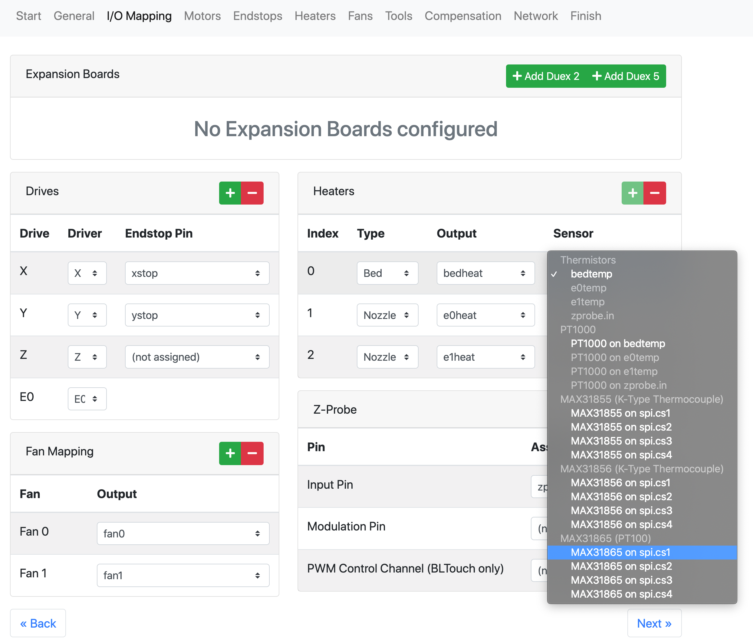
In the config tool you can select the PT100 channels from the sensor drop down in the I/O Mapping tab.
 Screen Shot 2022-07-14 at 3.51.31 PM.png
And here is a basic example config using 3 PT100 sensors one each for bed and 2 hot ends.
; Configuration file for Duet WiFi (firmware version 3.3) ; executed by the firmware on start-up ; ; generated by RepRapFirmware Configuration Tool v3.3.10 on Thu Jul 14 2022 15:54:51 GMT-0600 (Central Standard Time) ; General preferences G90 ; send absolute coordinates... M83 ; ...but relative extruder moves M550 P"My Printer" ; set printer name ; Network M552 S1 ; enable network M586 P0 S1 ; enable HTTP M586 P1 S0 ; disable FTP M586 P2 S0 ; disable Telnet ; Drives M569 P0 S1 ; physical drive 0 goes forwards M569 P1 S1 ; physical drive 1 goes forwards M569 P2 S1 ; physical drive 2 goes forwards M569 P3 S1 ; physical drive 3 goes forwards M569 P4 S1 ; physical drive 4 goes forwards M584 X0 Y1 Z2 E3:4 ; set drive mapping M350 X16 Y16 Z16 E16:16 I1 ; configure microstepping with interpolation M92 X80.00 Y80.00 Z400.00 E420.00:420.00 ; set steps per mm M566 X900.00 Y900.00 Z60.00 E120.00:120.00 ; set maximum instantaneous speed changes (mm/min) M203 X6000.00 Y6000.00 Z180.00 E1200.00:1200.00 ; set maximum speeds (mm/min) M201 X500.00 Y500.00 Z20.00 E250.00:250.00 ; set accelerations (mm/s^2) M906 X800 Y800 Z800 E800:800 I30 ; set motor currents (mA) and motor idle factor in per cent M84 S30 ; Set idle timeout ; Axis Limits M208 X0 Y0 Z0 S1 ; set axis minima M208 X230 Y210 Z200 S0 ; set axis maxima ; Endstops M574 X1 S1 P"xstop" ; configure switch-type (e.g. microswitch) endstop for low end on X via pin xstop M574 Y1 S1 P"ystop" ; configure switch-type (e.g. microswitch) endstop for low end on Y via pin ystop M574 Z1 S1 P"zstop" ; configure switch-type (e.g. microswitch) endstop for low end on Z via pin zstop ; Z-Probe M558 P0 H5 F120 T6000 ; disable Z probe but set dive height, probe speed and travel speed M557 X15:215 Y15:195 S20 ; define mesh grid ; Heaters M308 S0 P"spi.cs1" Y"rtd-max31865" ; configure sensor 0 as PT100 on pin spi.cs1 M950 H0 C"bedheat" T0 ; create bed heater output on bedheat and map it to sensor 0 M307 H0 B0 S1.00 ; disable bang-bang mode for the bed heater and set PWM limit M140 H0 ; map heated bed to heater 0 M143 H0 S120 ; set temperature limit for heater 0 to 120C M308 S1 P"spi.cs2" Y"rtd-max31865" ; configure sensor 1 as PT100 on pin spi.cs2 M950 H1 C"e0heat" T1 ; create nozzle heater output on e0heat and map it to sensor 1 M307 H1 B0 S1.00 ; disable bang-bang mode for heater and set PWM limit M143 H1 S280 ; set temperature limit for heater 1 to 280C M308 S2 P"spi.cs3" Y"rtd-max31865" ; configure sensor 2 as PT100 on pin spi.cs3 M950 H2 C"e1heat" T2 ; create nozzle heater output on e1heat and map it to sensor 2 M307 H2 B0 S1.00 ; disable bang-bang mode for heater and set PWM limit M143 H2 S280 ; set temperature limit for heater 2 to 280C ; Fans M950 F0 C"fan0" Q500 ; create fan 0 on pin fan0 and set its frequency M106 P0 S0 H-1 ; set fan 0 value. Thermostatic control is turned off M950 F1 C"fan1" Q500 ; create fan 1 on pin fan1 and set its frequency M106 P1 S1 H1 T45 ; set fan 1 value. Thermostatic control is turned on M950 F2 C"fan2" Q500 ; create fan 2 on pin fan2 and set its frequency M106 P2 S1 H2 T45 ; set fan 2 value. Thermostatic control is turned on ; Tools M563 P0 D0 H1 F0 ; define tool 0 G10 P0 X0 Y0 Z0 ; set tool 0 axis offsets G10 P0 R0 S0 ; set initial tool 0 active and standby temperatures to 0C M563 P1 D1 H2 F0 ; define tool 1 G10 P1 X0 Y0 Z0 ; set tool 1 axis offsets G10 P1 R0 S0 ; set initial tool 1 active and standby temperatures to 0C ; Custom settings are not defined