Sorry... but if you want to pay for the support, which is a nice idea, why not buy a real Duet board right away and also support the European economy and save jobs ?
Was just a thought. ")
Best posts made by Norder
-
RE: Software version 3.4.2 now availableposted in Firmware installation
-
Filament-Knot-Stop (KnotenStopp)posted in Filament Monitor
I hope this post is placed correctly?
If not ... moderator ... please postpone, thanks.I use Google-Translator for translating, so please apologize for the English.
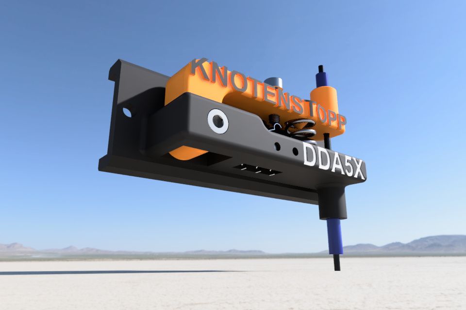
I invented a knot-stop (KnotenStopp) that stops printing when the filament is knotted.
I removed my filament-out-sensor from the printer a long time ago, because I can roughly estimate whether the filament on the spool is enough for certain prints.But I often have the problem that the filament gets tangled / knotted and I do not notice this filament jam and thus my 3D printing is ruined.
This "KnotenStopp" has a micro-switch from an old end-stop and is connected as a end-stop to the E1 end-stop connection on the Duet Wifi.
As soon as the filament is knotted, a tension is created on the filament... his pulling force triggers the switch and the 3D printer pauses.I posted the "KnotenStopp" on Thingiverse (+ video). By the way, it's my first upload to Thingiverse ... so if something doesn't work ... please understand.
Here is the link to the knot-stop (KnotenStopp): https://www.thingiverse.com/thing:4232477
Have fun with the knot-stop ... I hope it makes printing easier for you.
-
RE: suche deutschen support Großformat 3D-Drucker DUET2 WIFI-Boardposted in Firmware installation
@axiom
Moin Landsmann
Mein Englisch ist auch nicht besser geworden mit den Jahren als ich noch zur Schule ging... 1975
Ich nutze in meinem Browser ein Google Translate PlugIn damit ich weiter komme.Ich kenne jetzt die ganzen Problemlösungen nicht wie manch andere hier im Forum, die anscheinend jedes Problem aus der Welt schaffen können und von diesen Duet-Profis gibt es hier einige, daher solltest Du Dir ein Übersetzungs-PlugIn für Deinen Browser suchen der die komplette Seite übersetzen kann.
Oder nutze einfach die Webseite: https://translate.google.com/Zu Deinem Problem...
Ich habe auch dieses PT100 Tochterboard.
Verbunden habe ich es mit 4 auf 2 Kabel so wie es in der Anleitung steht, was wohl die Genauigkeit erhöht.Zu finden sind diese ganzen Anleitungen, Informationen und Hilfen auf den folgenden Seiten.
https://docs.duet3d.com/User_manual/Connecting_hardware/Temperature_connecting_thermocouples
Hier steht es mit dem 2- und 4 Kabel Anschlussmöglichkeiten.
https://duet3d.dozuki.com/Wiki/Connecting_PT100_temperature_sensorsAchte darauf welche Firmware Du benutzt, also ob 2.xx oder 3.xx.
Grüße von der Nordseeküste

----------- Translated Text -------------
Hello fellow countryman
My English didn't get any better over the years when I was still at school... 1975
I use a Google Translate plug-in in my browser to get further.I don't know all the solutions to problems like some others here in the forum, who seem to be able to solve any problem and there are some of these Duet professionals here, so you should look for a translation plugin for your browser that covers the entire site can translate.
Or simply use the website: https://translate.google.com/To your problem...
I also have this PT100 daughterboard.
I connected it with 4 to 2 cables as it says in the instructions, which probably increases the accuracy.All these instructions, information and help can be found on the following pages.
https://docs.duet3d.com/User_manual/Connecting_hardware/Temperature_connecting_thermocouples
Here it is with the 2 and 4 cable connection options.
https://duet3d.dozuki.com/Wiki/Connecting_PT100_temperature_sensorsPay attention to which firmware you use, i.e. whether 2.xx or 3.xx.
Greetings from the North Sea coast
-
RE: Mesh Probing not starts at Originposted in IR Height Sensor
@r3shy
According to your data, your probe is installed 37.5mm to the right of the nozzle and is 10mm above the nozzle (view from above of the print head).
The mistake is often made that a positive value is entered, although the probe is installed to the left of the nozzle, which would then be -37.5mm.
I think this is where your problem lies !?When you call G29, the sample offset data entered in G31 is automatically added / subtracted.
With the G30 you have to add or subtract the offset of the probe yourself.It looks like this to me...
The print bed has a size of 330mm x 330mm.; Axis Limits M208 X-14 Y-35 Z0 U0 S1 ; minimum M208 X330 Y330 Z360 U360 S0 ; maximum(Indicate actual size at maximum)
; IR-Probe
M558 K0 C"zprobe.in" P3 H1.7 F120 T10000 B1 A10 S0.010 R0.4
G31 K0 P500 X0.6 Y22.3 Z3.162
The probe is mounted 0.6mm to the right of the nozzle and 22.3mm above the nozzle (top view of the print head).
; grid / mesh
M557 X30:300 Y30:300 P9
I leave a margin of 30mm where the probe shouldn't or can't measure.
With G29, the first measuring point of the probe is exactly at X30 Y30 and 9 measurements are made from X30 to X300 (P9).I prefer the P parameter on the M557 command line because the distance is calculated automatically.
If you take the S parameter, as you did with S50, then a measuring point is set every 50mm. But then you have to measure the distance exactly to really measure the specified area.
In your case...
M557 X37.5:300 Y37.5:300 S50
Invoice:
300 - 37.5 = 262.5
262.5 / 50 = 5.25
5.25 measurements do not work.
If you want to scan the entire area of 262.5mm with the probe, the calculation would be:
262.5 : 5 = 52.5
So... M557 X37.5:300 Y37.5:300 S52.5Therefore the P parameter is simpler... you just specify how many measuring points you want and the distance is calculated automatically.
You should leave a small margin, say 10mm, then your M557 command line should look like this.
M557 X10:290 Y10:290 P5If the nozzle is exactly at X30 Y30 and I want to measure exactly this point with the IR probe, then I have to include the offset of the probe in the G30 command.
In my case the G30 command line would be like this:
G30 P0 X29.4 Y7.7 Z-99999 S-1Google Translate
-- Original Text --Nach Deinen Daten ist Deine Sonde 37,5mm rechts neben der Düse verbaut und liegt 10mm über der Düse (Blick von Oben auf den Druckkopf).
Oft wird der Fehler gemacht das ein positiver Wert eingetragen wird, obwohl die Sonde links neben der Düse verbaut ist, was dann -37,5mm wäre.
Ich glaube hier liegt Dein Problem !?Wenn Du G29 aufrufst, dann werden die Daten des Probe-Offsets automatisch addiert / subtrahiert die in G31 eingetragen sind.
Bei G30 musst Du den Offset der Sonde selber addieren bzw subtrahieren.Bei mir sieht es so aus...
Das Druckbett hat eine Größe von 330mm x 330mm.; Axis Limits M208 X-14 Y-35 Z0 U0 S1 ; minimum M208 X330 Y330 Z360 U360 S0 ; maximum(Bei Maximum die tatsächliche Größe angeben)
; IR-Probe
M558 K0 C"zprobe.in" P3 H1.7 F120 T10000 B1 A10 S0.010 R0.4
G31 K0 P500 X0.6 Y22.3 Z3.162
Die Sonde ist 0,6mm rechts neben der Düse und 22,3mm über der Düse montiert (Blick von Oben auf den Druckkopf).
; grid / mesh
M557 X30:300 Y30:300 P9
Ich lasse einen Rand von 30mm wo die Sonde nicht messen soll bzw kann.
Bei G29 ist der erste Messpunkt der Sonde genau bei X30 Y30 und es werden von X30 bis X300 9 Messungen gemacht (P9).Ich bevorzuge den Parameter P in der M557 Befehlszeile, da der Abstand automatisch ausgerechnet wird.
Nimmt man den S Parameter, so wie bei Dir mit S50, dann wird alle 50mm ein Messpunkt gesetzt. Man muss dann aber den Abstand genau ausmessen um wirklich den angegeben Bereich zu messen.
In Deinem Fall...
M557 X37.5:300 Y37.5:300 S50
Rechnung:
300 - 37,5 = 262,5
262,5 : 50 = 5,25
5,25 Messungen funktionieren nicht.
Möchte man den gesamten Bereich von 262,5mm mit der Sonde abtasten, dann wäre die Rechnung:
262,5 : 5 = 52,5
Also... M557 X37.5:300 Y37.5:300 S52,5Daher ist der P Parameter einfacher... man gibt nur an wieviel Messpunkte man möchte und der Abstand wird automatisch berechnet.
Du solltest einen schmalen Rand lassen, von sagen wir mal 10mm, dann müsste die M557 Befehlszeile wie folgt bei Dir aussehen.
M557 X10:290 Y10:290 P5Bin ich mit der Düse genau bei X30 Y30 und möchte genau diesen Punkt mit der IR-Probe messen, dann muss ich in dem G30 Befehl den Offset der Sonde mit einberechnen.
In meinem Fall würde die G30 Befehlszeile so lauten:
G30 P0 X29.4 Y7,7 Z-99999 S-1 -
RE: Input Shaping: Accelerometer not found.posted in Tuning and tweaking
The forum is big... very big.
But I found the information needed to hook up an accelerometer to a temperature sensor daughter board.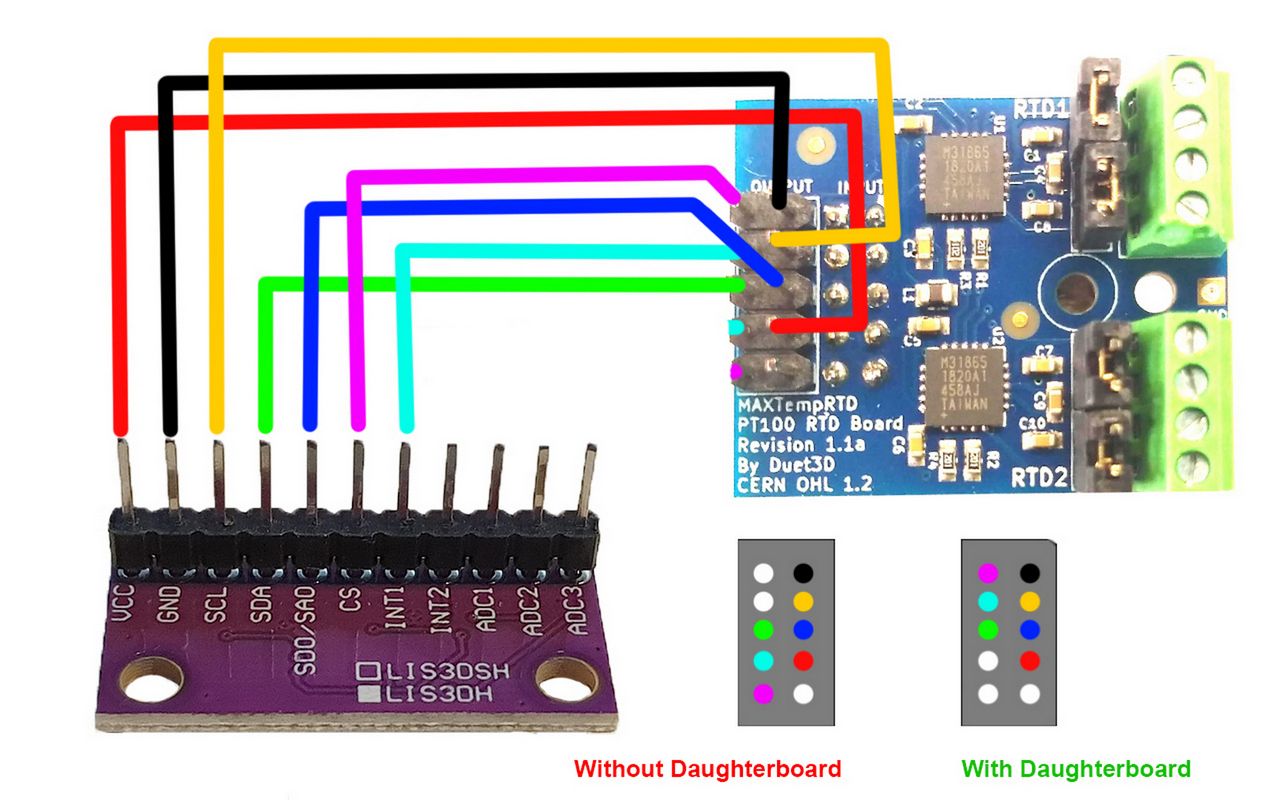
Google Translate
----- Original Text -----Das Forum ist groß... sehr groß.
Aber ich habe die nötigen Informationen gefunden um ein Beschleunigungsmesser auf ein Temperatursensor-Tochterbord anzuschließen.problem solved / Problem gelöst
-
RE: Could this height map offset be causing first layer issues?posted in Tuning and tweaking
@timsworkshop
Your config.g says...
M98 P"configs/probe_config.g" ; Config settings for my EZABL probeYou write but you have a BLTouch.
What is the content of the probe_config.g ?
Is it a mistake and you took over the config.g from another printer that had an EZABL sample or did you switch from EZABL to BLTouch and forgot to edit the entry ?Your config.g says...
M208 S0 X355 Y355 Z400 ; set axis maxima
but your bed.g says...
M557 X60:380 Y90:390 P20Is it possible that your BLTouch is mounted to the left of the nozzle and the following command line from your config.g is therefore wrong...
global probe_offset_x = 30 ; BL Touch X offset
and it has to be -30 instead ?P.S.:
global probe_offset_y = 36 ; BL Touch Y offset
Also here it could have to be -36 ?If the BLTouch is in front of and to the left of the nozzle, there must be minus values in the offset of the BLTouch.
Behind the nozzle and to the right are plus values. -
RE: Using DWC to make my own web interfaceposted in Duet Web Control
@thyrviklein
With this plugin BtnCmd from MintyTrebor (GitHub Link) you can create your own pages in DWC. -
RE: Could this height map offset be causing first layer issues?posted in Tuning and tweaking
@timsworkshop said in Could this height map offset be causing first layer issues?:
Thanks @Norder for the help!
very gladly.
Yes, that's exactly how it is... G29 takes the area you defined with M557 and adds or subtracts the offset values of the probe.
I have a 330x330 print bed and leave a 30mm free on the outer edge.
The reason for this is the BLTouch, which is mounted to the left of the nozzle and doesn't quite reach the right edge.
I have two Z-Probes, an IR-Probe from Duet and the BLTouch which I already had before the IR-Probe but didn't want to disassemble it because it has difficulties for some surfaces where the IR-Probe has difficulties such as glass surfaces or PEI and with rough surfaces.The IR probe is my main sensor so to speak and it would also go to the very edge of the print bed, but because I have an M557 command line that applies to both sensors and because I wanted the mesh to be the same size.
This is what my M557 command line looks like for the 330x330 print bed...
M557 X30:300 Y30:300 P9For example, if you want to probe the level screws of the print bed in a macro file, like I do to level the print bed "manually" via the level screws, then you have to convert the offset from the BLTouch yourself.
A macro to set one of the three level screws, for example, looks like this.
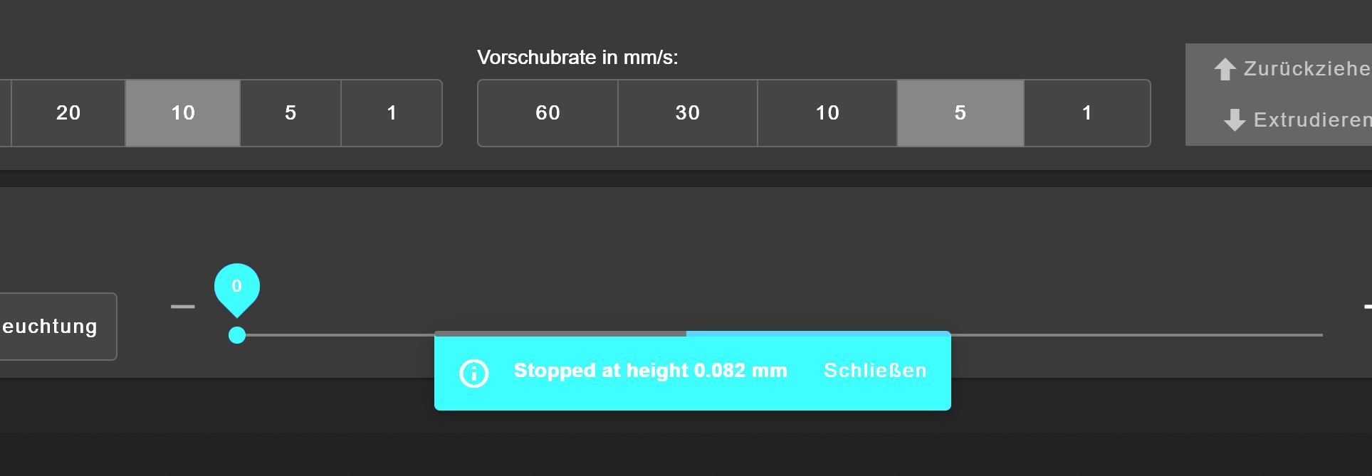
M561
G29 S2
M291 P"5-fache Messung - Links" R"IR-Probe" T3

G1 Z5 F10000
G1 X29.4 Y142.7 F10000
G30 S-1 K0 H3.162
G1 Z5 F10000

G4 P4000	; 4 Sekunde Pause

G1 Z5 F10000
G1 X29.4 Y142.7 F10000
G30 S-1 K0 H3.162
G1 Z5 F10000

G4 P4000	; 4 Sekunde Pause

G1 Z5 F10000
G1 X29.4 Y142.7 F10000
G30 S-1 K0 H3.162
G1 Z5 F10000

G4 P4000	; 4 Sekunde Pause

G1 Z5 F10000
G1 X29.4 Y142.7 F10000
G30 S-1 K0 H3.162
G1 Z5 F10000

G4 P4000	; 4 Sekunde Pause

G1 Z5 F10000
G1 X29.4 Y142.7 F10000
G30 S-1 K0 H3.162
G1 Z5 F10000
The measured height is shown on the display... if it says 0.082mm, for example, then I have to turn the level screw a little anti-clockwise... the second of five measurements then takes place and I try to get to 0.000, but with +- 0.010 I am more than satisfied because the MeshBedLeveling will come afterwards.
The z-offset entered in the config.g must also be entered in the macro file, so exactly 0.000 is displayed when the nozzle touches the bed.
This makes it easier to concentrate than having to hit the offset of 3,162, which you have to write down so you don't forget it or have to look in the config.g every time.I find this method of manual leveling better, because here you don't go by feel (0.05mm adjustment sheet or piece of paper as a leveling aid between bed and nozzle) and therefore leveling is more precise and I also find... faster.
I determined the Z offset with a 0.05mm measuring plate by positioning the nozzle 0.05mm above a level screw and then measuring this point 10x with a macro that was written especially for this purpose and where I then got the mean value of these measurements is displayed, which is then the Z offset.Yeah I know... I'm overdoing the leveling a bit.
But I just enjoy it.
Just a Hobby")
Little explained and much written... also a problem of mine.
 (Sorry!)
And the translation makes it look twice as much.Google Translate
-- Original Text --@timsworkshop said in Could this height map offset be causing first layer issues?:
Thanks @Norder for the help!
sehr gerne.
Ja, genau so ist es... G29 nimmt sich den Bereich vor den Du mit M557 definiert hast und addiert oder subtrahiert die Offset Werte der Sonde.
Ich habe ein 330x330 Druckbett und lasse einen 30mm am äußeren Rand frei.
Der Grund dafür ist der BLTouch der links neben der Düse montiert ist und nicht ganz bis an den rechten Rand kommt.
Ich habe zwei Z-Sonden, eine IR-Probe von Duet und den BLTouch den ich bereits vor dem IR-Probe hatte, ihn aber nicht demontieren wollte weil er für manche Oberflächen wo der IR-Probe Schwierigkeiten hat wie zB bei Glas-Oberflächen oder PEI und bei rauen Oberflächen.Der IR-Probe ist sozusagen mein Haupt Sensor und der würde auch bis an den äußersten Rand des Druckbettes kommen, aber weil ich eine M557 Befehlszeile habe die für beide Sensoren gilt und weil ich das Mesh gleich groß haben wollte.
So sieht meine M557 Kommandozeile für das 330x330 Druckbett aus...
M557 X30:300 Y30:300 P9Wenn Du zB in einer Makro Datei die Levelschrauben des Druckbettes sondieren möchtest, so wie ich es mache um das Druckbett "manuell" über die Level Schrauben zu leveln, dann musst Du das Offset vom BLTouch selber umrechnen.
Ein Makro um zB eine der drei Levelschraube einzustellen, sieht wie folgt aus.
(Makro siehe oben)Auf dem Display wird mir die gemessene Höhe angezeigt... steht dort zB 0.082mm dann muss ich die Levelschraube etwas gegen den Uhrzeigersinn drehen... es erfolgt dann die zweite von fünf Messungen und ich versuche auf 0.000 zu kommen, aber mit +- 0.010 bin ich mehr als zufrieden denn es kommt danach ja noch das MeshBedLeveling.
(Screenshot siehe oben)
Den Z-Offset der in der config.g eingetragen ist, muss auch in die Makro Datei eingetragen werden, so wird exakt 0.000 angezeigt wenn die Düse das Bett berührt.
So kann man sich einfacher konzentrieren als wenn man den Offset von 3.162 treffen müsste den man notieren müsste damit man ihn nicht vergisst oder man jedes mal in der config.g nachsehen müsste.Ich finde diese Methode des manuellen Levelns besser, da hier nicht nach Gefühl (0,05mm Einstellblech oder Stück Papier als Level-Hilfe zwischen Bett und Düse) gegangen wird und somit das leveln exakter und ich finde auch.... schneller geht.
Den Z-Offset habe ich mit einem 0,05mm Messblech ermittelt indem ich die Düse 0,05mm über einer Levelschraube positioniert habe und dann diese Stelle mit einem Makro welches speziell für diesen Zweck geschrieben wurde, 10x gemessen und wo mir dann der Mittelwert dieser Messungen angezeigt wird, was dann der Z-Offset ist.Ja ich weiß... ich übertreibe es mit dem Leveln ein wenig.
Aber es macht mir halt Spaß.
Hobby ebenWenig erklärt und viel geschrieben... auch so ein Problem von mir.
(Entschuldigung !)
Und durch die Übersetzung sieht es gleich doppelt so viel aus. -
RE: how to turn off all fans at the end of printposted in Gcode meta commands
@ratrig0331 said in how to turn off all fans at the end of print:
what is I wanted to tell it to turn on at a certain layer height? Is that possible?
Inserting a GCode from a specific layer is easy with PrusaSlicer.
Here's an example...
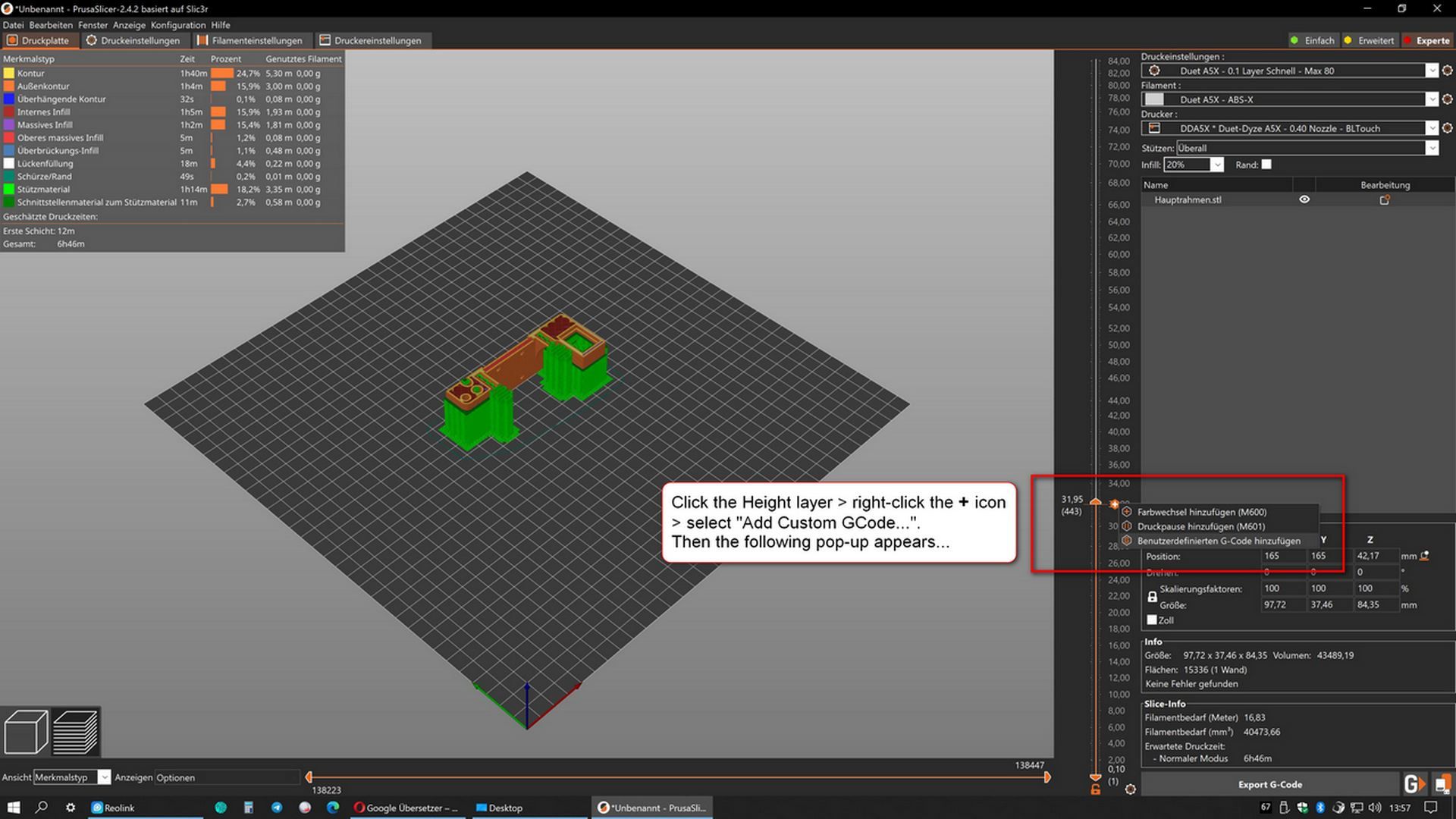
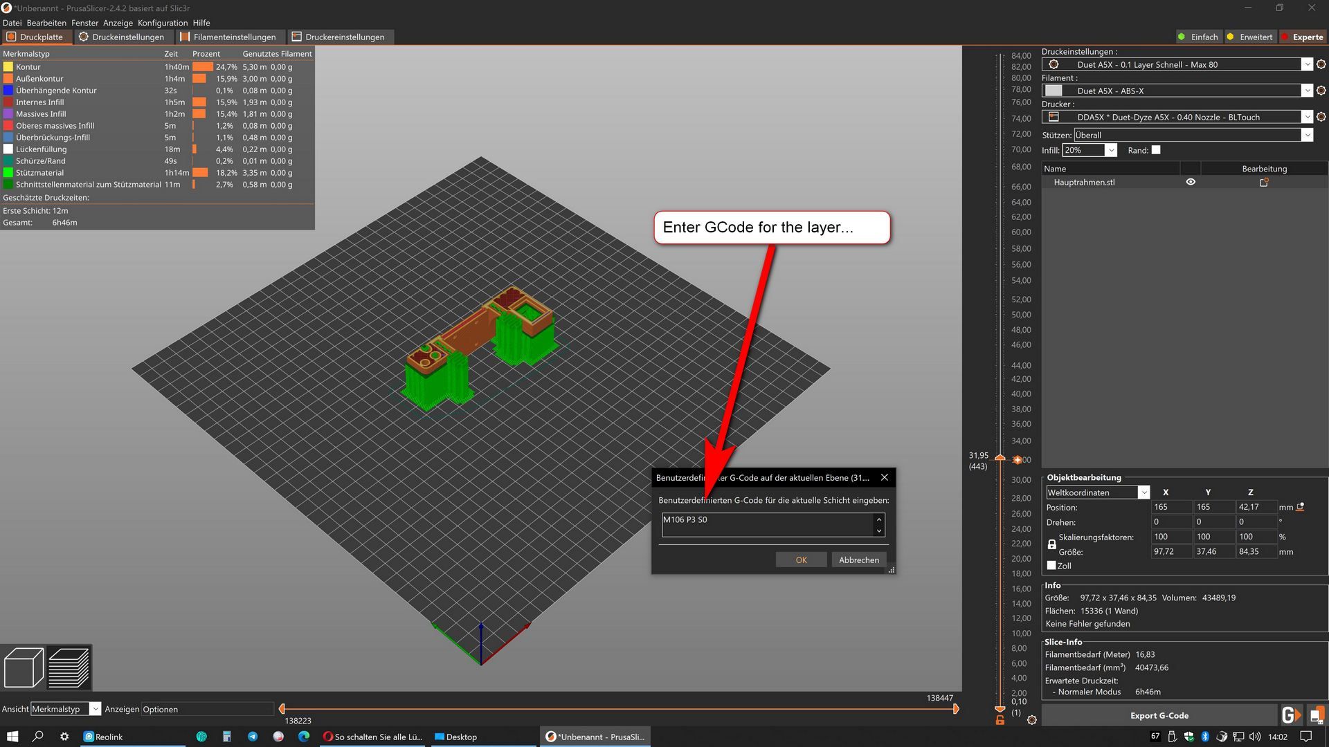
I don't know which slicer you use, but maybe it will help you ?
Google Translate
--- Original Text ---Das einfügen eines GCode ab einem bestimmten Layer ist mit dem PrusaSlicer ganz einfach.
Hier ein Beispiel...
(Siehe Screenshots)Ich weiß zwar nicht welchen Slicer Du nutzt, aber vielleicht hilft es Dir weiter ?
Latest posts made by Norder
-
RE: Filament Dryingposted in 3D Printing General Chat
Storing Filaments:
About 5-6 spools of filament are stored in a vacuum bag which also contains some silica gel drying bags and a hydrometer that is clearly visible.
About 12 filament rolls with nylon and ABS are stored in a large plastic box in which about 2kg of silica gel are scattered at the bottom and are covered with a plastic fly screen so that no silica gel beads get into the filament rolls.Filament during printing:
When I print, the filament roll is placed in a drying oven lying flat. In this drying oven I installed a ball-bearing mounted thread roll in which the filament roll is clamped.
The filament is guided from the drying oven to the print head in a transparent PTFE tube so that it is never exposed to humidity and dust in the room air.The drying oven is insulated inside with 19mm insulating foam (Armaflex) and there are about 15 of these silica gel bags in the bottom of the oven, which keep the humidity low for a long time, so that a filament roll can be stored there for 2-3 days between the prints
In the lid of the drying oven I made the exhaust air openings variably adjustable and used a hydrometer.
The dehydrator can heat up to 70°C but I run it on the lowest setting so that it reaches around 45°C.Humidity is at best 18% to 25%. If it rises above 35% in the vacuum bags or in the large box, I remove the silica gel and dry it in a dry air fryer, into which a large sieve fits exactly, in which about 1kg of silica gel fits.
I mostly print ABS and Nylon. Next comes PETG and PLA is last for me.
Photos of the dehydrator:
1 / 2 / 3 / 4 / 5 / 6 / 7 / 8Google Translate
--- Original Text ---Filamente Aufbewahren:
Etwa 5-6 Filamentrollen lagern in einem Vakuumbeutel in dem auch einige Silika-Gel Trocknungsbeutel und ein gut sichtbarer Hydrometer liegen.
Etwa 12 Filamentrollen mit Nylon und ABS lagern in einer großen Kunststoffbox in der unten etwa 2kg Silika-Gel ausgestreut sind und mit einem Fliegengitter aus Kunststoff abgedeckt sind so dass keine Kügelchen des Silika-Gel in die Filamentrollen gelangen.Filament während des Druckens:
Wenn ich drucke, dann kommt die Filamentrolle liegend in einen Dörrofen. In diesem Dörrofen habe ich eine kugelgelagerte Gewinderolle eingebaut in der die Filamentrolle eingespannt wird.
Das Filament wird aus dem Dörrofen bis zum Druckkopf in einem durchsichtigen PTFE Schlauch geführt so dass es zu keiner Zeit der Luftfeuchtigkeit und dem Staub der Zimmerluft ausgesetzt ist.Der Dörrofen ist innen mit 19mm Dämm-Schaumstoff (Armaflex) isoliert und es liegen etwa 15 dieser Silik-Gel Beutel unten im Ofen die die Luftfeuchtigkeit über eine längere Zeit niedrig halten, so dass dort eine Filamentrolle auch mal 2-3 Tage lagert zwischen den Prints.
Im Deckel des Dörrofen habe ich die Abluftöffnungen variabel einstellbar gemacht und ein Hydrometer eingesetzt.
Der Dörrofen kann bis 70°C heizen aber ich betreibe ihn auf der niedrigsten Stufe so dass in etwa 45°C erreicht wird.Die Luftfeuchtigkeit liegt im besten Fall bei 18% bis 25%. Steigt sie in den Vakuumbeuteln oder in der großen Box über 35% dann entnehme ich das Silika-Gel und trockne es in einer Trockenluftfriteuse wo exakt ein großes Sieb hinein passt in dem etwa 1kg Silika-Gel passt.
Ich drucke zum größten Teil ABS und Nylon. Danach kommt PETG und PLA liegt bei mir auf dem letzten Platz.
-
RE: David's IR Sensor: Questionsposted in General Discussion
@br7408
Regarding the falsified measurement results of the BLTouch due to the disturbing magnetic fields... I once posted something about this with a solution that works quite well, depending on which metal you use.
Maybe it will help you ?Link to Thread:
https://forum.duet3d.com/topic/29491/hint-bltouch-incorrect-measurement-due-to-magnetic-print-bed?_=1682329087880Google Translate
--- Original Text ---Zu den verfälschten Messergebnissen des BLTouch wegen der störenden Magnetfeldern... dazu habe ich mal etwas gepostet mit einer Lösung die je nachdem welches Metall man nimmt, ganz gut funktioniert.
Vielleicht hilft es Dir weiter ?Link zum Thread:
https://forum.duet3d.com/topic/29491/hint-bltouch-incorrect-measurement-due-to-magnetic-print-bed?_=1682329087880 -
RE: David's IR Sensor: Questionsposted in General Discussion
@br7408
I use two sensors (BLTouch & dc42's IR Probe).
I only use the BLTouch on print surfaces where the IR probe has its problems.
99% of the time the IR probe is in use.I have a matte black GRP (glass fiber reinforced plastic) FR4 from Printbay.
It is the Blackprint, as already mentioned, it is matt black and has no imprints such as a company logo or any stripes or patterns.I've been using this Blackprint for a few years and it's still just as great as it was on day one.
I mainly print nylon and ABS.
The Blackprint has no trouble with ASA.The plate consists of a magnet system (magnetic plate for the aluminum bed and the flexible black print itself is also magnetic.
It should work with your existing magnetic board.Printbay also manufactures to measure and has sizes over 500x500mm.
Printbay video of me.
Here I show how the "matched pair technique" of the blackprint works.
The magnetization of the plate is "strip-like" and thus the plate is always exactly aligned horizontally.
But normal spring steel PEI plates also work for me, but then this strip-shaped magnetization is not available and the PEI plate can be moved "continuously" even though it is held magnetically.I can only recommend this Blackprint. In addition, of all the records I know, she looks the hottest.
I hope I could show you something new.
Please write here which record you last chose.
Purely out of curiosity and interestGoogle Translate
----- Original Text -----Ich nutze zwei Sensoren (BLTouch & dc42's IR Probe).
Den BLTouch nutze ich nur bei Druckoberflächen wo der IR-Probe seine Probleme mit hat.
Zu 99% ist der IR-Probe im Einsatz.Ich habe eine mattschwarze GFK (Glasfaserkunststoff) FR4 von Printbay.
Es ist die Blackprint, sie ist wie bereits erwähnt, mattschwarz und hat keinerlei Aufdrucke wie zB ein Firmenlogo oder irgendwelche Streifen und Muster.Ich nutze diese Blackprint schon einige jahre und sie ist noch genau so toll wie am ersten Tag.
Ich drucke hauptsächlich Nylon und ABS.
Mit ASA hat die Blackprint keine Schwierigkeiten.Die Platte besteht aus ein Magnetsystem (Magnetplatte für das Alubett und die biegsame Blackprint ist selber auch magnetisch.
Sie sollte mit Deiner bestehenden Magnetplatte funktionieren.Printbay fertigt auch auf Maß und hat Größen über 500x500mm.
Printbay Video von mir.
Hier zeige ich zeige wie die "Matched Pair Technik" der Blackprint funktioniert.
Die magnetisierung der Platte ist "streifenförmig" und somit ist die Platte horizontal immer exakt ausgerichtet.
Bei mir funktionieren aber auch normale Federstahlblech PEI Platten, dann ist diese streifenförmige magnetisierung aber nicht vorhanden und die PEI Platte kann "stufenlos" verschoben werden obwohl sie magnetisch gehalten wird.Ich kann diese Blackprint nur empfehlen. Zudem sieht sie von allen Platten die ich kenne... am geilsten aus.
Ich hoffe ich konnte Dir etwas neues zeigen.
Bitte schreibe hier, für welche Platte Du Dich zuletzt entschieden hast.
Rein aus Neugier und Interesse -
RE: DC42 IR probeposted in IR Height Sensor
@downshift64
Did you "manually" level your print bed before retrieving the mesh?If I get this error message, the print bed has shifted, so I have to level it manually on the level wheels.
This can happen when the print surface has been reground or a different bed temperature has been set and the print bed has a different expansion.
Some cross holders (holder between the print bed and the printer frame) bend when a printing plate is cleaned with excessive pressure.So take a piece of paper or a feeler gauge with 0.05mm or 0.1mm thickness and level the print bed with the bed level screws.
Paper or feeler gauge between nozzle and print bed.Then you call up the mesh again with G29.
Google Translate
-- Original Text --Hast Du Dein Druckbett "manuell" gelevelt bevor Du das Mesh abgerufen hast ?
Wenn ich diese Fehlermeldung bekomme, hat sich das Druckbett verstellt, so dass ich es manuell an den Levelrädern leveln muss.
Das kann passieren wenn die Druckoberfläche neu geschliffen wurde oder eine andere Betttemperatur eingestellt ist und das Druckbett eine andere Ausdehnung hat.
Manche Kreuzhalter (Halterung zwischen Druckbett und Druckerrahmen) verbiegen sich wenn eine Druckplatte mit zu hohem Druck gereinigt wird.Nimm also ein Blatt Papier oder eine Fühllehre mit 0,05mm oder 0,1mm Stärke und level das Druckbett mit den Bettlevelschrauben.
Papier bzw Fühllehre zwischen Düse und Druckbett.Danach rufst Du erneut das Mesh mit G29 ab.
-
RE: Stutter on long curves - bitrate?posted in Firmware installation
@IndeX4D
In the Cura settings... is RepRap set for the "GCode Flavor" ?
It can be found in the printer settings, where the start and end GCode is also entered.
(Settings -> Printer -> Manage Printers... -> Machine Settings).@T3P3Tony
I added a M413 S0 to stop power loss like somebody said. was not working. may that´s the reason it looked like it was not printing.
I´ll start a print, now.M413 does not know the duet.
You probably mean M911: Configure auto save on loss of power (Duet GCode Dictionary Link) !? -
RE: Heating speed control methodposted in Tuning and tweaking
@Dennis_kim Have you already done a PID tuning?
The title should be in English so you can get help. At first I thought it was spam.
-
RE: PT100 DAUGHTER BOARD, Reading 2000 c for Heat Bedposted in Duet Hardware and wiring
@ScaraMan Hi,
Please post some information about the heating mat used on the print bed... which thermistor is installed there?
Then I would strongly recommend you to update to the latest firmware. -
RE: Turn off the z-axis limit switchposted in Tuning and tweaking
@Proschi78
With this command you switch the axis limit on or off.
https://docs.duet3d.com/en/User_manual/Reference/Gcodes#m564-limit-axes
However, the project should be treated with caution! -
RE: Print ABS in vase mode w/o chamber?posted in General Discussion
@o_lampe
I mainly print ABS and Nylon.
As @deckingman correctly mentioned, ABS does not like drafts, you should also do without the fan and if so, then only work with some cooling on overhangs.
Large objects are also no problem.
But I think it depends on the ABS itself whether the pressure is successful.
I use ABS-X from Minadax and rTitan from FormFutura.
rTitan is recycled TitanX, which is cheaper through recycling.
ABS-X and rTitan have Warp-Free technology and do not smell.
I still have a cheap ABS from China, but you can't print it without extraction, the gases constrict your throat.
I print ABS and Nylon with no enclosure, but with the window closed and no fan.