Tool and Probe offsets
-
Hello everyone,
I am wondering if someone can confirm how the tool and z probe offsets should be set up correctly? My X and Y axis are zeroed by the extruder carriage intercepting the X and Y endstops, using that zero point i have input the nozzle coordinate as plus 59 in X and plus 56 in Y. My BLtouch is sitting at plus 102 in X and plus 61 in Y, however my reading of the documentation is my probe coordinate should be set from the tool giving 43 in X and 5 in Y from the tool head.
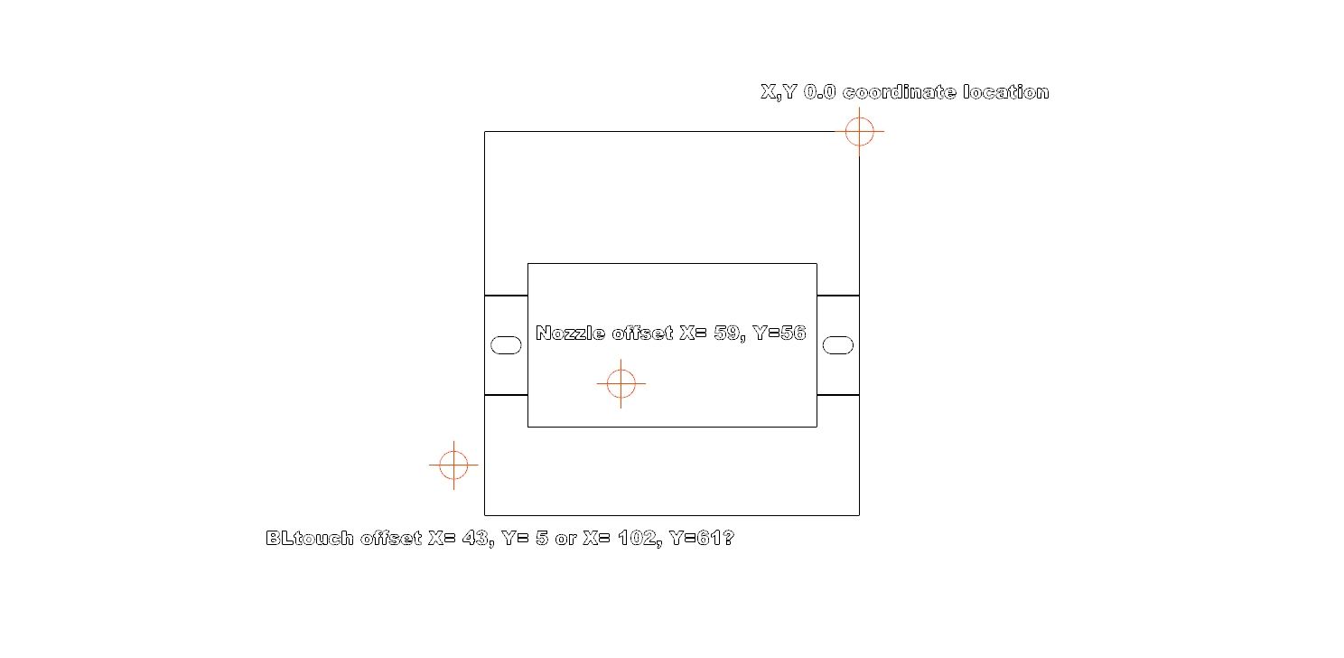
"1X and Y offsets of the Z probe relative to the print head (i.e. the position when the empty tool is selected) can be specified. This allows you to calculate your probe coordinates based on the geometry of the bed, without having to correct them for Z probe X and Y offset."
Sorry if this seems obvious but my experience with CMM would be to set the datums and zero point and everything is referenced off that.
Cheers,
Dan -
@daniel-armstrong This topic is of deliberate complexity - let’s make it simple:
You have a printer with a single tool. To print something, the slicer commands the nozzle to points in the 3-dimensional print area. This print area is defined as the space within which the nozzle can reach every single point.
So it is a good idea to start with the print area: X/Y/Z origin and min./max. ranges of all axes. This coordinate system relates to the tip of your nozzle; again: to keep it simple, avoid tool offsets if you don’t need them.
Now come the endstops. They don’t limit the print area, they are just needed to get a known coordinate for each axis when the Duet boots up. After that, you define your print area relative to these coordinates. Then, you can happily forget them.
This way, you are free to define the origin of your print area - on my printer, X0/Y0 is in the center of the bed, so that I can use all four quadrants, but that’s up to you. It’s all about how you can best imagine this printable area - no offsets, no endstops involved.
Nevertheless, you will need to define one single offset: the distance (X/Y) of your BLTouch to the nozzle. Then, RepRap Firmware will take care of the calculations.
-
So the following is from my config.g file,
; Axis Limits
M208 X200 Y90 Z150 S0 ; set axis maxima and high homing switch positions
M208 X-59.83 Y-56.05 Z0 S1 ; set axis minima and low homing switch positions; Tools
M563 P0 D0 H1 F0 ; Define tool 0
G10 P0 X0 Y0 Z0 ; Set tool 0 axis offsets
G10 P0 R0 S0 ; Set initial tool 0 active and standby temperatures to 0C
M207 S1.2 F1200 ; set 1.2mm retract distance for G10 command;Touch Probe
M950 S0 C"exp.heater3" ; define probe servo pin
M558 P9 C"^zprobe.in" H5 F100 T2000 ; BLTouch Probe
G31 P50 X43.07 Y4.68 Z1.355 ; Set Z probe trigger value, offset and trigger height - Increase Z value to move bed closer to nozzleFrom you explanation the tool nozzle is assumed to be the 0,0 point by default and you need to define the difference between this 0,0 and where the endstops trigger?
-
From you explanation the tool nozzle is assumed to be the 0,0 point by default and you need to define the difference between this 0,0 and where the endstops trigger?
Not quite. I propose the nozzle has no offset on the coordinate your slicer wants to print at. However, its position can be anywhere in the print area. This means that the slicer doesn't need to know about tool offsets.
Now to the print area which is defined with
M208gCodes. In your config, you have this:M208 X200 Y90 Z150 S0 ; set axis maxima and high homing switch positions M208 X-59.83 Y-56.05 Z0 S1 ; set axis minima and low homing switch positionsYou don't define the 'homing switch positions' as the comment says. That is done with
M574which is missing from your snippet. Please post that section of your config.g or tell me where you have placed your endstops.With
M208, you define the print area relative to 0/0 - as I told you, you are free to put the origin of the coordinate system wherever you think it's most intuitive. Here's a reference how this works.Given you use the right-hand coordinate system (which you normally should in order not to mirror your prints), your X origin is 59.83 mm away from the left side of either your endstop (if it is low-end) or the bed, and your Y origin is 56.05 mm away from the front (of either a low-end endstop or the bed). Is that your intention?
As a side note: your numbers are way too precise, I can't imagine you to handle 1/100 mm with mechanical switches. Usually, dealing with millimetres is sufficient.
The simple approach assumes the endstops to be within the printable area. If they are not, you have to take care of that in your homing files. In case you need this, we can go through that later - just let me know.
-
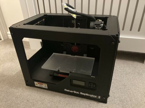
Yeah the intention is for the end stops to be positioned in the right rear corner of the printer (replicator 2 conversion) if looking at it from the front as in the image below.
config.g
; General preferences
M111 S0 ; Debugging off
G21 ; Work in millimetres
G90 ; Send absolute coordinates...
M83 ; ...but relative extruder moves
M555 P2 ; Set firmware compatibility to look like Marlin; Axis Limits
M208 X200 Y90 Z150 S0 ; set axis maxima and high homing switch positions
M208 X-59.83 Y-56.05 Z0 S1 ; set axis minima and low homing switch positions; Enable Panel Due Connector
M575 P1 S1 B57600 ; Enables connector and sets baud rate; Endstops- Switches
M574 X1 S1 P"!xstop" ; X min active high endstop switch
M574 Y1 S1 P"!ystop" ; Y min active high endstop switch
M574 Z1 S1 P"!zstop" ; Z min active high endstop switch - Config for hard Z Endstop;Touch Probe
M950 S0 C"exp.heater3" ; define probe servo pin
M558 P9 C"^zprobe.in" H5 F100 T2000 ; BLTouch Probe
G31 P50 X43.07 Y4.68 Z1.355 ; Set Z probe trigger value, offset and trigger height - Increase Z value to move bed closer to nozzleM557 X0:200 Y0:90 S10 ; Define mesh grid
; Drives
M569 P0 S0 ; Drive 0 goes backwards
M569 P1 S0 ; Drive 1 goes backwards
M569 P2 S1 ; Drive 2 goes forwards
M569 P3 S1 ; Drive 3 goes forwards
M569 P4 S1 ; Drive 4 goes forwards
M584 X0 Y1 Z2 E3 ; set drive mapping
M350 X16 Y16 Z16 E16 I1 ; Configure microstepping with interpolation
M92 X88.573186 Y177.78 Z400 E409 ; Set steps per mm
M566 X900 Y900 Z300 E1200 ; Set maximum instantaneous speed changes (mm/min)
M203 X1080000 Y1080000 Z600 E96000 ; Set maximum speeds (mm/min)
M201 X1000 Y1000 Z100 E2000 ; Set accelerations (mm/s^2)
M906 X900 Y1000 Z400 E1200 I30 ; Set motor currents (mA) and motor idle factor in per cent
M84 S30 ; Set idle timeout; Heaters
M308 S0 P"bedtemp" Y"thermistor" T100000 B3974 C0 R4700 ; configure sensor 0 as thermistor on pin bedtemp
M950 H0 C"bedheat" T0 ; create bed heater output on bedheat and map it to sensor 0
M140 H0 ; map heated bed to heater 0
M143 H0 S120 ; set temperature limit for heater 0 to 120C
M308 S1 P"e0temp" Y"thermistor" T100000 B4725 C7.06e-8 ; configure sensor 1 as thermistor on pin e0temp
M950 H1 C"e0heat" T1 ; create nozzle heater output on e0heat and map it to sensor 1
M143 H1 S280 ; set temperature limit for heater 1 to 280CM307 H0 R0.261 K0.401:0.000 D3.11 E1.35 S1.00 B0 ; Set PID values for Heatedbed - derived from autotune
M307 H1 R1.219 K0.254:0.000 D6.15 E1.35 S1.00 B0 V19.9 ; Set PID values for Extruder 1 - derived from autotune; Network
M550 P"Duet_Rep2X" ; Set machine name
;M551 P"XXXXX" ; Set password
M552 S1 ; Enable network
;M552 P192.168.0.98 ;Fixed IP Address
;M554 P192.168.0.1 ;Gateway
;M553 P255.255.255.0 ;Netmask; Access point is configured manually via M587 by the user
M586 P0 S1 ; Enable HTTP
M586 P1 S1 ; Enable FTP
M586 P2 S0 ; Disable Telnet; Fans
M950 F0 C"fan0" Q500 ; Set fan 0 value, PWM signal inversion and frequency.
M106 P0 T45 H1 ; Set fan 0. Thermostatic control is turned on at 45 celcius.
M106 P0 S0 ; Switch cooling fan off; Accelerometer
M955 P0 C"spi.cs3+spi.cs4"; Tools
M563 P0 D0 H1 F0 ; Define tool 0
G10 P0 X0 Y0 Z0 ; Set tool 0 axis offsets
G10 P0 R0 S0 ; Set initial tool 0 active and standby temperatures to 0C
M207 S1.2 F1200 ; set 1.2mm retract distance for G10 command; Select Tool
T0; Custom settings are not configured
homex.g
; Lift Z relative to current position
G91
G1 Z5 F150000 H2
G90; Move quickly to X axis endstop and stop there (first pass)
G1 X-290 F1800 H1; Go back a few mm
G91
G1 X5 F150000
G90; Move slowly to X axis endstop once more (second pass)
G1 X-290 F360 H1; Lower Z again
G91
G1 Z-5 F150000 H2
G90homey.g
; Lift Z relative to current position
G91
G1 Z5 F150000 H2
G90; Move quickly to Y axis endstop and stop there (first pass)
G1 Y-155 F1800 H1; Go back a few mm
G91
G1 Y5 F150000
G90; Move slowly to X axis endstop once more (second pass)
G1 Y-155 F360 H1; Lower Z again
G91
G1 Z-5 F150000 H2
G90homeall.g
; Relative positioning
G91; Lift Z
G1 Z5 F600 H2; Course home X and Y
G1 X-290 F1800 H1
G1 Y-155 F1800 H1; Move away from the endstops
G1 X5 Y5 F150000; Fine home X and Y
G1 X-290 Y-155 F360 H1; Code for Hard Endstop home Z
; Move Extruder out of the way
;G90
;G1 X-12 Y-10 F150000
; Home Z against hard enstop
;G91
;G1 Z-200 F400 H1 ; rough home Z axis;G1 Z2 F400 ; move down by 2mm
;G1 Z-155 F40 H1 ; fine home z axis
; Adjust Z distance from Z endstop
;G92 Z0.00 ; positive - Move bed closer to extruder, negative - Move bed away from extruder; Absolute positioning
G90; Code for Sensor Based Z Homing
; Go to first bed probe point and home Z
G1 X63 Y16 F150000
G30; Uncomment the following line to lift the nozzle after probing
G1 Z5 F300 H2 -
Yeah the intention is for the end stops to be positioned in the right rear corner of the printer
Fine. Next step is to define the X/Y origin of your print area. Following this link (from my latest post) and using the right hand rule, two „natural“ options are common: front/left or center. Your choice. Then, we can elaborate the values for
M208andM574. -
So iv poured over that link for some time and it seems my solution has to be two minus values in the X/Y to account for the trigger position of the end stops then simply define the maximum print area the nozzle can reach.
; Axis Limits
M208 X200 Y90 Z150 S0 ; set axis maxima and high homing switch positions
M208 X-60 Y-56 Z0 S1 ; set axis minima and low homing switch positions; Enable Panel Due Connector
M575 P1 S1 B57600 ; Enables connector and sets baud rate; Endstops- Switches
M574 X1 S1 P"!xstop" ; X min active high endstop switch
M574 Y1 S1 P"!ystop" ; Y min active high endstop switch
M574 Z1 S1 P"!zstop" ; Z min active high endstop switch - Config for hard Z Endstop;Touch Probe
M950 S0 C"exp.heater3" ; define probe servo pin
M558 P9 C"^zprobe.in" H5 F100 T2000 ; BLTouch Probe
G31 P50 X43 Y5 Z1.355 ; Set Z probe trigger value, offset and trigger height - Increase Z value to move bed closer to nozzleM557 X0:200 Y0:90 S10 ; Define mesh grid
-
@daniel-armstrong said in Tool and Probe offsets:
it seems my solution has to be two minus values in the X/Y to account for the trigger position of the end stops
It hasn't to be. The origin is independent of the endstops. Why not define it front/left? Then, you can operate with positive coordinates, which, IMHO, is much more convenient. For your config, this means:
; Axis Limits M208 X259 Y146 Z150 S0 ; set axis maxima M208 X0 Y0 Z0 S1 ; set axis minima ; Endstops- Switches M574 X2 S1 P"!xstop" ; X max active high endstop switch M574 Y2 S1 P"!ystop" ; Y max active high endstop switch (only modified lines). Of course, I can't verify the coordinate values. Just test where you get with an absolute move to X0 Y0 and change the numbers in
M208if you don't arrive at the front left corner of your bed.For your homing files (Z excluded), this means to apply a positive distance for the relative moves towards the endstops, as these are now "high-end".
Talking about homing: You can perform all moves in relative mode (
G91), so that you just need oneG90at the end. Sample files can be found here. -
Does this need changes to the m569 command for motor direction? The behavior i now have while testing this on the X axis is the axis will home away from the end stop or if negative values are used in the homex.g will home towards the endstop perform the correct back off and re-trigger operation then wont let me jog the carriage in a negative direction only further in to the endstop.
-
Does this need changes to the m569 command for motor direction?
That's well possible. From here, I can't see how the steppers turn. With the origin at front/left, the head must move to the rear/right with positive coordinates. Given the maxima I used with
M208meet your printer's size, the print head should arrive at the endstops if you enterG1 X259 Y146in the console - that is, after homing.Note that for relative moves (within your homing files, enclosed in
G91/G90), negative values are used to move towards the origin at 0/0, positive values to go towards the endstops. -
@infiniteloop
Thank you for all the help, i now have all the homing moves going in the correct direction and a 0,0 point set at front left of the bed. The final issue turned out to be the X,Y motor directions, so a quick reverse of the M569 command got it all moving correctly.Thanks again for the patience in explaining all this.
Dan.
-
@daniel-armstrong Glad I could help.