Suddenly I have no connection to my board
-
@infiniteloop yes
-
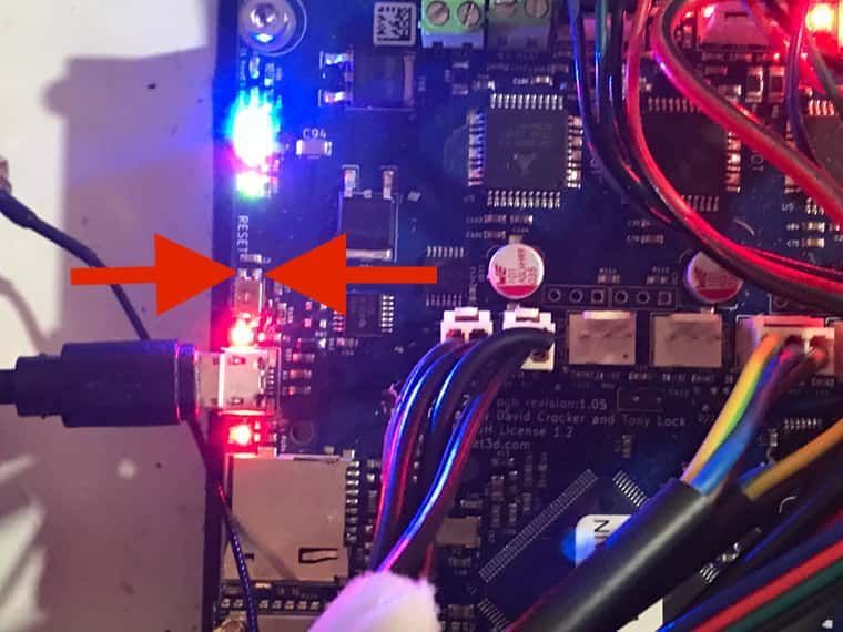
@axiom can you post a (good) photo with all LEDs on the left side of the board, including the SD card socket? Please take this when the board is powered so that we can see the LEDs.
-
@infiniteloop
Only USB-Connection:
 Connected with power supply:
-
-
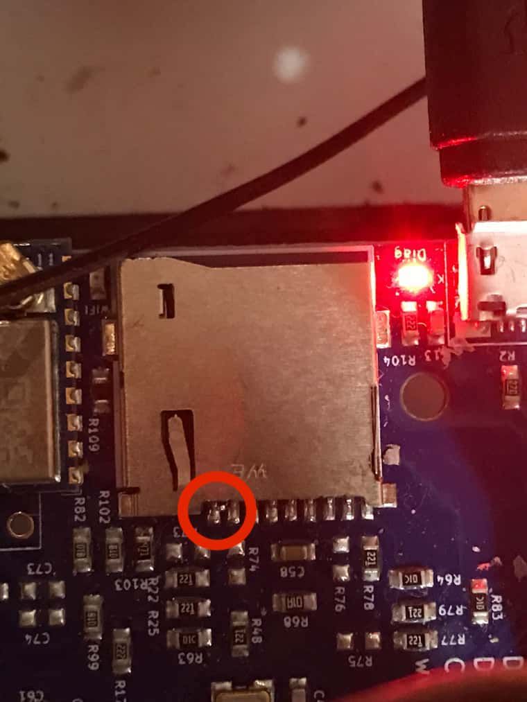
@axiom To test the reset button, first remove power from the board. Then, measure resistance between the contacts marked in the photo.

This is very difficult with the usual measuring probes. Furthermore, the tips may not touch the metal housing of the switch - I recommend putting an adhesive strip on the side facing the contacts.
In order to verify the measurement, you need someone who presses the button once during the measurement: only then may the measured resistance be 0. Else, it must be near infinite.
Measure carefully and try several times so that you can be sure of the result.
-
@infiniteloop The resistance is 1, I can't measure when the button is pressed because the button broke (see above)
-
The resistance is 1, I can't measure when the button is pressed because the button broke (see above)
Sure I read that, but I didn't know that the button got stuck. Looks like it has to be replaced …
EDIT:
The resistance is 1
What does this mean with your multimeter: "near 0" or "open"?
-
@infiniteloop 0 means open load - idle, 1 means resistance is present but not within the measuring tolerance
-
0 means open load - idle, 1 means resistance is present but not within the measuring tolerance
I already noticed that you own a very interesting multimeter: Usually, 0 Ohm is what you read from a short - or from a pressed button.
In other words: if your measurement was properly done and the reading (e.g. "1") is correct, probability is high that your reset button is not stuck in.
-
@infiniteloop No, it can't get stuck because I pulled it out with tweezers as described in troubleshooting, unfortunately I can't put it back in because it broke off. Can the knob or switch be replaced individually? Can I continue to work without the switch for the time being? The question is, is there any hope that the board will get a connection again with this initial situation and why does the Diag LED still light up red. I've tried with and without the SD card, endstops in and out, etc. Any ideas on how to proceed?
-
@infiniteloop When troubleshooting, it says that if the LED lights up red, the firmware may have to be reinstalled. i took a new sd card, but maybe the sd card reader is not working? I still can't establish a connection via USB cable, the port is not recognized
-
Can the knob or switch be replaced individually?
Knob: No. Switch: Yes.
Can I continue to work without the switch for the time being?
Yes. If a reset of the board should be required, you can simply shorten the two contacts I pointed you at with a screwdriver.
The question is, is there any hope that the board will get a connection again with this initial situation and why does the Diag LED still light up red.
Good question. According to the link @dc42 pointed you at, we can assume that the firmware doesn't load.
I've tried with and without the SD card, endstops in and out, etc. Any ideas on how to proceed?
Yes. In a first step, you should ensure that VIN is not connected, i.e. the board should only be powered via USB. Then, proceed with the steps under "Connect to a PC via USB and look for the port".
If you don't see any valid port on your PC, try different USB cables: some of these don't contain signal lines, they just supply power.If you are still out of luck, continue with the section "If the port still doesn't appear on the PC". But please don't erase the firmware until you are instructed by @phaedrux or the other guys from Duet3D to do so, because I am not sure whether there are less critical options to try first.
-
Had something happened to the reset switch to cause damage?
Had it ever been used? -
From DC42:
It's very unlikely that the reset switch went short-circuit and that was the cause of the problem. However, without the reset switch it won't be easy to erase the firmware to allow it to be programmed with Bossa. I suggest he starts by connecting it to a PC over USB and see if the Bossa port appears. If it doesn't, he could carefully short the two pins if the reset switch in the photo together for a few seconds, and see if the port appears.
In the unlikely event that the reset switch is shorted, the Bossa port will appear. Uploading firmware over Bossa will appear to succeed, but if if you run Verify in Bossa, it will fail to verify.
-
@axiom OK, you got the Go!
When troubleshooting, it says that if the LED lights up red, the firmware may have to be reinstalled. i took a new sd card, but maybe the sd card reader is not working?
Forget the SD card for a moment. RRF consists of several pieces - in the case of your Duet, we talk about the code which resides in the MCU. This is called "firmware" in a narrow sense, it must be flashed onto the board in order to bring that back to work.
The troubleshooting section "If the port still doesn't appear on the PC" is the first reading, it tells you how to connect with BOSSA over USB. In this context, read what DC42 has to tell you (see @Phaedrux' latest post).
Next reading is "Fallback procedure #2" in the document "Installing and Updating Firmware". Read this carefully before you start, it's crucial to fully understand these instructions. If you are in doubt: ask.
-
@infiniteloop I thought about the reset button again. If the resistance isn't 0, doesn't that mean the button is constantly trying to reset? Or is that the other way around?
Otherwise, the question would be how I can interrupt the circuit at this point, right? -
I thought about the reset button again. If the resistance isn't 0, doesn't that mean the button is constantly trying to reset? Or is that the other way around?
It's all about these two contacts:
If they are connected (or "shorted"), the board will reset. If they are not connected, resistance will be high (many Ohms), that's an "open" switch or, in other words, the button is not pressed.
The question would be how I can interrupt the circuit at this point, right?
Both DC42 and me pointed you on that:
However, without the reset switch it won't be easy to erase the firmware to allow it to be programmed with Bossa. I suggest he starts by connecting it to a PC over USB and see if the Bossa port appears. If it doesn't, he could carefully short the two pins if the reset switch in the photo together for a few seconds, and see if the port appears.
If a reset of the board should be required, you can simply shorten the two contacts I pointed you at with a screwdriver.
-
@infiniteloop But I think the opposite is the case, that the contact is not broken but constantly connected
-
But I think the opposite is the case, that the contact is not broken but constantly connected
According to your measurements, the contacts are open. In case this proves to be wrong, you will know that at the end of the BOSSA session, as DC42 tells you:
In the unlikely event that the reset switch is shorted, the Bossa port will appear. Uploading firmware over Bossa will appear to succeed, but if if you run Verify in Bossa, it will fail to verify.
-
@infiniteloop I did the fallback procedure step by step (with jumper etc. (several times) diag LED was on solid and a port/connection could not be created....