Accelerometer not working Duet 2 Wifi
-
I have the following specs:
- Board: Duet 2 WiFi (2WiFi)
- Firmware: RepRapFirmware for Duet 2 WiFi/Ethernet 3.4.1 (2022-06-01)
- Duet WiFi Server Version: 1.26
Going on day 4 with this... I know my wiring is correct, as I've checked it multiple times, then 3 times over. All solders points are good, crimps are good, verified everything with a multimeter, even personally pulled and checked every jst crimp, re-crimping new connectors on any questionable ones. I'm using a 1.5 meter USB 3 cable. I have the wires soldered directly into the LIS3DH (ADA2809) board, cable sheathing soldered to GND. At the Duet side, I have the wires terminating into short, 200mm jst cables that plug into the Duet Temp Daughterboard pins (even tried wrapping them in alum foil). I have every wire color coded from end-to-end to make certain no mistakes were made. ("Error: M955: Accelerometer not found on specified port"). After being certain of the wiring, on day 2, I thought perhaps I have a bad accelerometer so I ordered a 2nd. Got it, wired it one up, and ("Error: M955: Accelerometer not found on specified port"). The light does come on on the LIS3DH (I have pin 8 on the Duet going into VIN on the LIS3DH, and I have verified my Duet is putting out 3v on this pin).
Then I found the post about the resistor, so I soldered a 330 Ohm resister in series with the SDO at the LIS3DH side. ("Error: M955: Accelerometer not found on specified port"). Then I found the post about perhaps a small capacitor may help wired between GND and SCL, so I tried that. ("Error: M955: Accelerometer not found on specified port").
Thought perhaps my short jst runs were the issue, so I ordered and made new connectors directly on the USB3 wires and now the Duet side of the USB3 cable terminates directly into the Temp Daughterboard.
Short of suspecting something is wrong with the Temp Daughterboard, I'm not sure what else to do. I've been at this for 4 days: taking breaks, coming back, reading more posts, verifying wiring again. Also attempted to swap CS and INT from spi_cs4 and spi_cs3 then changed my M955 command, no avail. Even tried wiring up CS to cs5 on the expansion board. Nope. (yes, changed M955 in config)
If anyone has any suggestions outside of the posts already in this forum, I would so appreciate the help. Thank you in advance.
-
@onerob Not sure if there was a "special" config if you connect the accelerometer on daughter board...
Can you post your config.g please? -
Also, M122 results in case you wanted to see them:
M122
=== Diagnostics ===
RepRapFirmware for Duet 2 WiFi/Ethernet version 3.4.1 (2022-06-01 21:05:28) running on Duet WiFi 1.02 or later
Board ID: 0JD0M-9P6M2-NWNS0-7J1DJ-3SD6N-KT3ML
Used output buffers: 3 of 26 (15 max)
=== RTOS ===
Static ram: 23860
Dynamic ram: 75308 of which 260 recycled
Never used RAM 9796, free system stack 180 words
Tasks: NETWORK(ready,13.2%,242) HEAT(notifyWait,0.0%,317) Move(notifyWait,0.0%,363) MAIN(running,86.7%,444) IDLE(ready,0.1%,30), total 100.0%
Owned mutexes: WiFi(NETWORK)
=== Platform ===
Last reset 00:25:43 ago, cause: power up
Last software reset at 2022-08-23 18:09, reason: User, GCodes spinning, available RAM 10036, slot 1
Software reset code 0x0003 HFSR 0x00000000 CFSR 0x00000000 ICSR 0x0041f000 BFAR 0xe000ed38 SP 0x00000000 Task MAIN Freestk 0 n/a
Error status: 0x00
Aux0 errors 0,0,0
Step timer max interval 0
MCU temperature: min 24.4, current 34.8, max 36.3
Supply voltage: min 23.9, current 24.1, max 24.5, under voltage events: 0, over voltage events: 0, power good: yes
Heap OK, handles allocated/used 99/0, heap memory allocated/used/recyclable 2048/4/4, gc cycles 0
Events: 0 queued, 0 completed
Driver 0: standstill, SG min n/a
Driver 1: standstill, SG min n/a
Driver 2: standstill, SG min n/a
Driver 3: standstill, SG min n/a
Driver 4: standstill, SG min n/a
Driver 5:
Driver 6:
Driver 7:
Driver 8:
Driver 9:
Driver 10:
Driver 11:
Date/time: 2022-08-24 01:52:44
Cache data hit count 4294967295
Slowest loop: 5.15ms; fastest: 0.19ms
I2C nak errors 0, send timeouts 0, receive timeouts 0, finishTimeouts 0, resets 0
=== Storage ===
Free file entries: 10
SD card 0 detected, interface speed: 20.0MBytes/sec
SD card longest read time 3.3ms, write time 0.0ms, max retries 0
=== Move ===
DMs created 83, segments created 0, maxWait 0ms, bed compensation in use: none, comp offset 0.000
=== MainDDARing ===
Scheduled moves 0, completed 0, hiccups 0, stepErrors 0, LaErrors 0, Underruns [0, 0, 0], CDDA state -1
=== AuxDDARing ===
Scheduled moves 0, completed 0, hiccups 0, stepErrors 0, LaErrors 0, Underruns [0, 0, 0], CDDA state -1
=== Heat ===
Bed heaters 0 -1 -1 -1, chamber heaters -1 -1 -1 -1, ordering errs 0
Heater 1 is on, I-accum = 0.0
=== GCodes ===
Segments left: 0
Movement lock held by null
HTTP is idle in state(s) 0
Telnet is idle in state(s) 0
File is idle in state(s) 0
USB is idle in state(s) 0
Aux is idle in state(s) 0
Trigger is idle in state(s) 0
Queue is idle in state(s) 0
LCD is idle in state(s) 0
Daemon is idle in state(s) 0
Autopause is idle in state(s) 0
Code queue is empty
=== Filament sensors ===
Extruder 0 sensor: ok
=== Network ===
Slowest loop: 15.78ms; fastest: 0.00ms
Responder states: HTTP(0) HTTP(0) HTTP(0) HTTP(0) FTP(0) Telnet(0), 0 sessions
HTTP sessions: 1 of 8- WiFi -
Network state is active
WiFi module is connected to access point
Failed messages: pending 0, notready 0, noresp 0
WiFi firmware version 1.26
WiFi MAC address f4:cf:a2:71:b3:f7
WiFi Vcc 3.32, reset reason Power up
WiFi flash size 2097152, free heap 26616
WiFi IP address 192.168.1.100
WiFi signal strength -61dBm, mode 802.11n, reconnections 0, sleep mode modem
Clock register 00002002
Socket states: 0 0 0 0 0 0 0 0
- WiFi -
-
@onerob Please look at this post (scroll down) and check if your wiring is correct.
https://forum.duet3d.com/topic/29410/input-shaping-accelerometer-not-found/3?_=1661187418835 -
@cosmowave Thank you @cosmowave. Yes I've referred to that post (and 1 or 2 others with the same or similar diagram) and confirmed the wiring many times (to the point of insanity).
-
@onerob So it looks like 5th time's the charm. I decided to scrap it all and start from scratch, got it working and I'm actually collecting data! The new build consisted of:
- another new accelerometer (they're relatively cheap and if the old ones are actually good they'll definitely get used)
- a new (different) USB3 cable
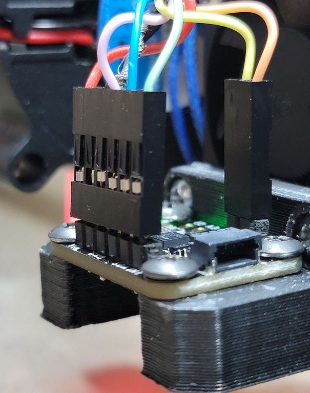
- soldered posts with jst connectors at the accelerometer
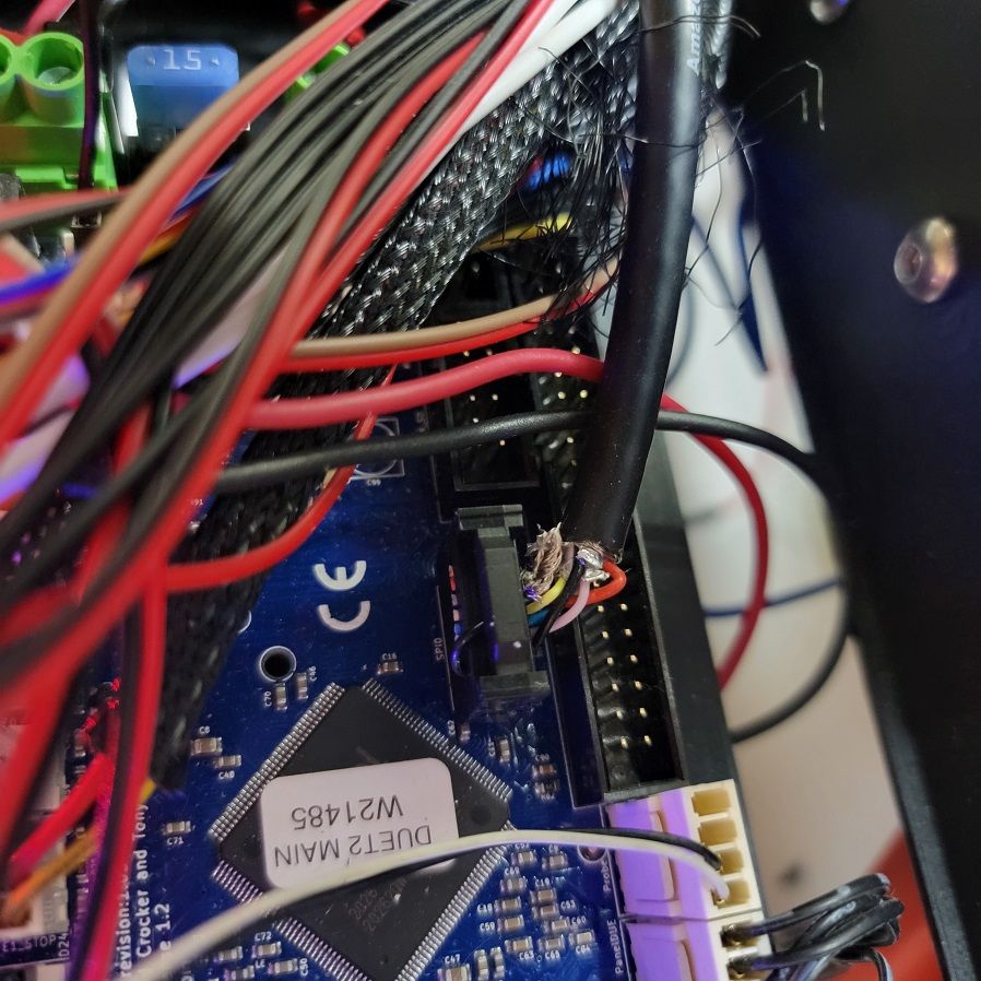
- ribbon cable plug at the Duet (ended up tearing apart an old ribbon cable plug and reusing it - see pic).
@cosmowave thank you for your responses, they were much appreciated.
-
@onerob
Hello, I'm the one who posted the drawing of the pinouts linked here.
Great that your accelerometer is working now.
This is how I did it with the USB3 cable.
I had a different data cable before, but it didn't work.I connected the CS pin to two wires of a USB3 cable.
These two wires are twisted together in the USB3 cable and have their own shielding.
So the line for the CS channel has its own shield.
This CS channel is very sensitive to electromagnetic interference.I connected the GND (ground) pin to a normal wire and cut off the meshes of the shielding of the entire cable at the cable ends.
I reused the connector on the daughterboard pins from an old computer cable.
And since the cables were too thick for these contacts with the cutting blades that cut through the sheathing of the cables, I bent these contacts outwards and soldered the cables to them and finally poured hot glue around the entire connector and shaped it.
Unfortunately I didn't take any photos of the bent contacts because this connector is now more stable than before.Google Translate
--- Original Text ---Hallo, ich bin der, der die Zeichnung der Pinbelegungen gepostet hat, die hier verlinkt wurde.
Toll, das Dein Beschleunigungssensor jetzt funktioniert.So habe ich das mit dem USB3 Kabel gemacht.
Vorher hatte ich ein anderes Datenkabel, welches aber nicht funktioniert hat.Ich habe bei mir den CS Pin an zwei Adern eines USB3 Kabels angeschlossen.
Diese beiden Adern sind im USB3 Kabel miteinander verdrillt und haben eine eigene Abschirmung.
So hat die Leitung für den CS Kanal seine eigene Abschirmung.
Dieser CS Kanal ist sehr empfindlich gegen elektromagnetische Störungen.Den GND (Grund) Pin habe ich mit einer normalen Ader verbunden und die Maschen der Abschirmung des kompletten Kabels an den Kabelenden abgeschnitten.
Den Stecker auf dem Tochterboard Pins habe ich von einem alten Computerkabel wiederverwendet.
Und da die Kabel zu dick waren für diese Kontakte mit den Schneideklingen die durch die Ummantelung der Kabel schneidet, habe ich diese Kontakte nach außen gebogen und die Kabel darauf verlötet und zum Schluss den gesamten Stecker mit Heißkleber umgossen und in Form gebracht.
Leider habe ich davon umgebogenen kontakten keine Fotos gemacht, denn dieser Stecker ist jetzt stabiler als vorher.DDA5X... 0.9° Stepper... Linearrails... Duet 2 Wifi... PT100 Board... Duet IR-Probe... Dyze Pro Kit up to 500°C.. etc
Thingiverse -
@norder Thanks for the info! Yeah I have the CS wire (orange in my case) running by itself (it's paired up with shielding and an unused white wire). Then I have the shielding from that soldered to the cable shielding and both terminated with the GND at BOTH ends. It's working consistently now and I'm just now getting ready to do some input shaping.
If it hadn't been for this forum and everyone who contributed to this topic in one form or another I'd be dead in the water, so a BIG THANK YOU to all of you (of course a special shout out to @dc42 )!!
-
An info about the input shaping with the Duet.
Input shaping is integrated in the DWC.
It becomes visible as soon as the acceleration sensor is successfully set up with M955 in config.g.But you should then install the input shaping plugin (Version 3.4.1-b1 / GitHub Link) from @chrishamm.
Only then can the input shaping data be conveniently compared, managed and configured.If input shaping with the Duet is new to you... maybe this info is too !?

Google Translate
--- Original Text ---Eine Info noch zu dem Input Shaping mit dem Duet.
Im DWC ist Input Shaping ja integriert.
Es wird sichtbar sobald in der config.g der Beschleunigungssensor erfolgreich mit M955 eingerichtet ist.Man sollte aber danach das Input Shaping PlugIn (Version 3.4.1-b1 / GitHub Link) von @chrishamm installieren.
Erst damit kann man die Input Shaping Daten konfortabel vergleichen, verwalten und konfigurieren.Wenn Input Shaping mit dem Duet neu für Dich ist... ist es diese Info vielleicht auch !?