Mixing Ratio Sliders DWC
-
Hi all. Is there anyway to bring up sliders on the DWC to control mixing ratio for multiple extruder drives for a tool?
Thanks.
-
That's a tricky thing: keeping the overall extrusionrate at 100% while moving one of three (or more) sliders.
Maybe it's possible with BTNCMD a project of @MintyTrebor -
@ravs99 said in Mixing Ratio Sliders DWC:
Hi all. Is there anyway to bring up sliders on the DWC to control mixing ratio for multiple extruder drives for a tool?
Thanks.
I can't see how that could be done. Let's assume you have 3 extruders with a mixing ratio of say 0.2:0.3:0.5. The sum of the 3 must always add up to 1.0. otherwise you would end up with either under or over extrusion. So if you had a slider that could increase the ratio for the first extruder, how would you decide which combination of the other two extruders should be reduced to maintain the overall ratio of 1.0? In the example above, if the first extruder was set to 0 3, then one or other or both of the second and third extruders would need to be reduced proportionally. How do you decide which? 0.3:0.2:0.5, 0.3:0.3:0.4, 0.3:25:0.45 would all be valid as would many other combinations.
-
@deckingman There could be a lock checkbox beside every slider.
Or there is an apply button, grayed out until the mixing ratio is 1.0 (some mixing scenarios wouldn't even need to be fixed at 100%, like purging ) -
@o_lampe said in Mixing Ratio Sliders DWC:
@deckingman There could be a lock checkbox beside every slider.
Or there is an apply button, grayed out until the mixing ratio is 1.0 (some mixing scenarios wouldn't even need to be fixed at 100%, like purging )With a 3 input hot end, there are something like a million potential combinations of mixing settings using 1% increments. With 4, 5 and 6 inputs, the number of combinations is crazy. The only way I can see sliders helping is with a 2 input hot end where one could use the range from 0 to 100. (i.e. from 0:100 to 100:0). So altering one extruder would automatically make an inverse adjustment to the other. With respect, but if you had ever used a mixing hot end, you wouldn't suggest not respecting the 100% rule - even for purging. Trust me, I know from lengthy experience............
-
@deckingman I trust your experience and for loading/unloading all filaments simultaneously a simple macro would do...
But no matter how many inputs or combinations, the apply button would call a short macro, which scales down (or up) all the sliders proportionally to 100%.
E. g. slider settings are 0.5/0.5/0.5, they would be scaled to 0.33/0.33/0.33 a.s.o.Using a lock checkbox would freeze this sliders value, making it even easier to adjust the ratio.
The sliders could also have programmable increments like the baby step buttons. -
@o_lampe Let's assume that you started with a mixing ratio of 0.1:0.3:0.6 and you wanted to change that to say 0.3:0.4:0.3. Using your method, you'd first change the first filament to 0.3. Then lock that filament. Then you hit apply which would respect the 0.3 for the first filament but change the second and third to 0.2 and 0.5 respectively. So at this point, you have 0.3:0.2:0.5. So then you change extruder 2 to give you the 0.4, then lock that one. But you'd also have to then limit the slider for extruder 2 to prevent the user from entering a value that would result in an extrusion amount greater than 100%. Then you hit apply again. That's bad enough but what about a 5 (or in my case 6) input hot end? You'd have to change the first extruder, lock it, hit apply, change the second, lock it, hit apply, change the third, lock it, hit apply, change the fourth, lock it, hit apply, and finally change the fifth and hit apply. Alternatively, you could change and lock a number of filaments at the same time but then you'd have to check that the user has respected the overall 100% rules. What action does the macro then take if that rule has been broken?
Although it could be done, it's extremely complicated, both in the implementation and from a user perspective. Much easier to simple send a single M567 IMO.
-
@deckingman @o_lampe Thank you for the insightful discussion. One thing I forgot to mention that I'm using the mixing ratio functionality in a different way. Im using a pellet extruder attached to an external feeder. For now, I have assigned the feeder as a second extruder so that it synchronously feeds pellets to thew pellet extruder. This is not the ideal approach and I would have done it through meta G code commands but I'm waiting for async movement to be a thing in RRF 3.5 so I gotta stick with mixing ratios for now. Thus I do not need the sum to add up to 1,etc
Sorry for that haha
-
@ravs99 the mixing ratios have been working for me for the most part. I just wanted to know if there is any easy way of bringing up sliders in the DWC for fine tuning
-
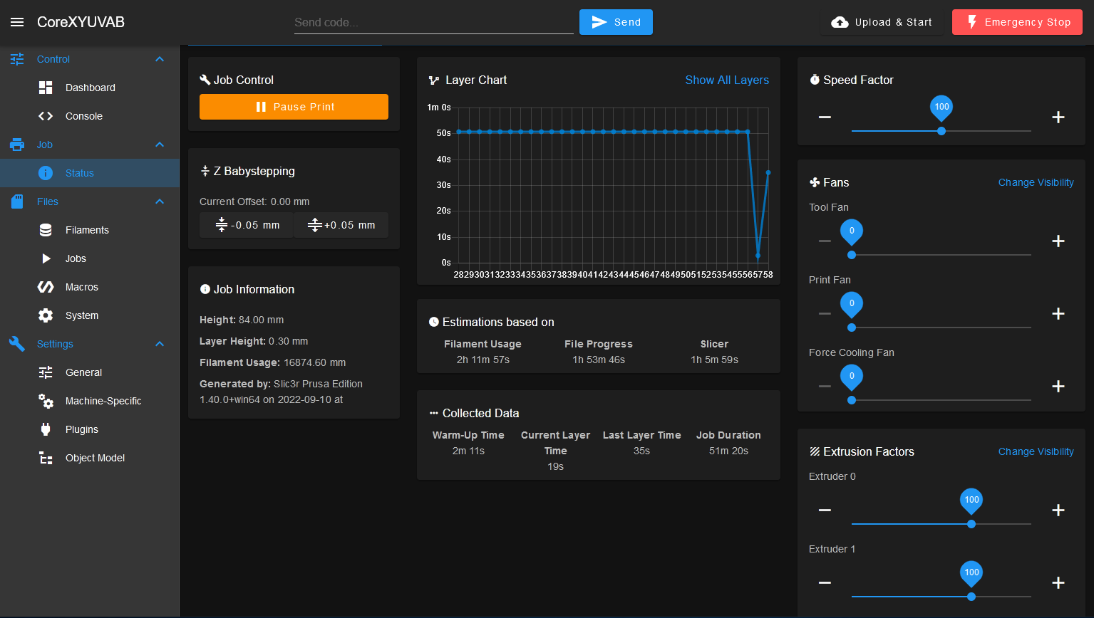
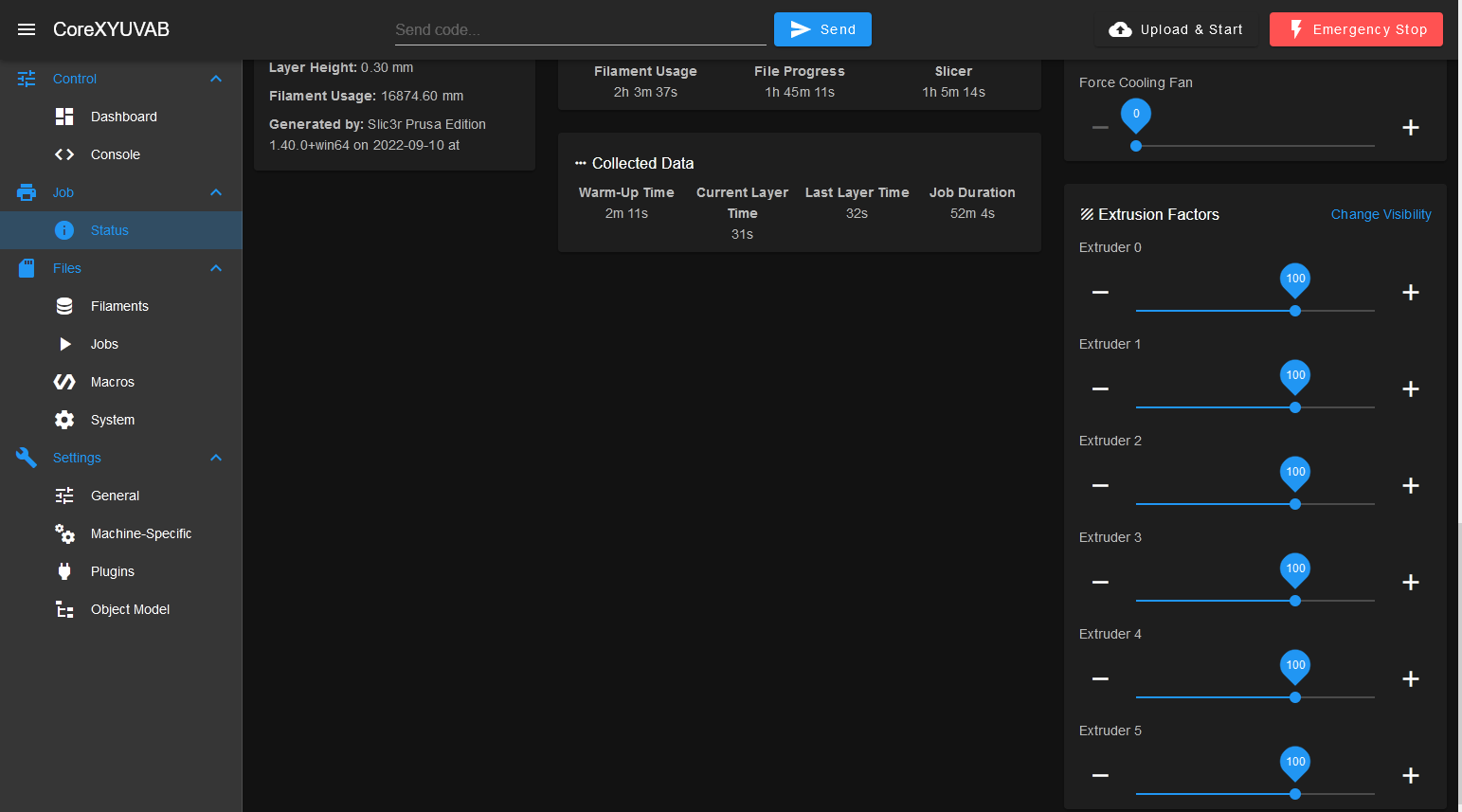
@ravs99 So this is nothing to do with mixing ratio. In which case, will the existing extruder override percentage sliders not do what you want?
-
@deckingman existing sliders? I do not seem to find any. maybe I have it setup wrong? Heres my config file.
; Enable network
M552 P129.100.228.115 S1
M550 P"hangprinter" ; change the name from the IP address of 192.168.50.2

;General Machine Settings/Conventions
G21 ;work in mm
G90 ;absolute coordinates
M83 ;relative extruder moves
;G4 S2 ; wait for expansion boards to start


;Heaters and Temp Sensor
 ;bandheater
  M140 H-1                                ; disable heated bed (overrides default heater mapping)
  M308 S1 P"temp0" Y"pt1000" A"Extruder Sensor"; configure sensor 1 as PT1000 on pin temp0 pin on DUET3
  M950 H1 C"out1" Q10 T1                    ; create nozzle heater output on out1 and map it to sensor 1, limit pwm frequency to 10Hz
  M307 H1 B0 R0.319 C1028.9 D36.57 S1.00 V12.1 ; AUTOTUNE RESULTS, PASTE M307 LINE HERE
  M143 H1 S300                            ; set temperature limit for heater 0 to 240C

  ;second temp sensor
  M308 S2 P"temp1" Y"pt1000" A"Barrel Sensor"; configure sensor 2 as PT1000 on pin temp1. FOR MONITORING ONLY, NO OTHER FUNCTIONALITY ASSOCIATED


;Fans
  ;Heatsink Fans 1 and 2
  M950 F1 C"!out4+out4.tach" Q25000 ; Fan 1 uses out4, but we are using a PWM fan so the output needs to be inverted, and using out4.tach as a tacho input
  M106 P1 H-1
  M950 F2 C"!out5+out5.tach" Q25000 ; Fan 2 uses out5, but we are using a PWM fan so the output needs to be inverted, and using out5.tach as a tacho input
  M106 P2 H-1

;Kinematics and Drives
  ;Drives: x4 NEMA23's for Hangprinter Axis and x1 NEMA17 for extruder

  M18                    ;disable default driver assignments;
  M569 P0 S0       ; drive 0 for extruder axis
  M569 P1 S0       ; drive 1 for D axis, goes forwards; need to create another "U" axis for D motor
  M569 P2 S1       ; drive 2 (Z motor output aka C) goes forwards
  M569 P3 S1       ; drive 3 (Y motor output aka B) goes forwards
  M569 P4 S1       ; drive 4 (X motor output aka A) goes forwards
  M569 P5 S0       ; drive 5 (feeder motor) goes backwards (CW looking from behind motor )
  M584 X4 Y3 Z2 E0:5 U1   ;assign drives to axes and create U axis for D motor. Feeder motor is assigned as a second extruder hence E0:5 where 5 is stepper drive 5 which feed motor is connected

 ;Step settings
  M350 X16 Y16 Z16 U16 E16:16 I1 ; configure microstepping with interpolation
  ;M92 X192 Y192 Z192  U192     ; set steps/mm for each spool. DO NOT CHANGE THIS PARAMETER
  M92 E1000:100                     ; set steps/mm for extruder and feed motor

 ;Speed and Accelerations
  M566 X250.00 Y250.00 Z250.00 U250.0 E200.00:200            ; set maximum instantaneous speed changes (mm/min)
  M203 X6000.00 Y6000.00 Z6000.00 U6000.00 E9000.00:1000.00        ; set maximum speeds (mm/min)
  M201 X500.00 Y500.00 Z500.00 U250.00 E200.00:200.00           ; set accelerations (mm/s^2)

 ;Set Currents
 M906 X2500 Y2500 Z2500 E1500:1000 U2500 I30 ; set motor currents (mA) and motor idle factor in per cent
 M84 S30 ; Set idle timeout


 ;Kinematics
 M669 K6 ; Configures the Duet 3 to identify as Hangprinter Kinematics

 ;set anchor distances
 M669 K6 A0.0:-792.0:-232.0 B730.0:413.0:-232.0 C-711.0:413.0:-232.0 D0.0:0.0:2298.0 ; set Hangprinter kinematics parameters
 M669 P900.0                               ; Hangprinter printable radius (unused for now)
 M669 S100 T0.5                             ; Segments per second and min segment length

 M666 Q0.0033333                           ; buildup compensation factor for ABCD
 M666 R75.0:75.0:75.0:75.0                 ; ABCD radii
 M666 U2:2:2:4                    ; Mechanical advantages on ABCD spools - 2 stands for doubled lines
 M666 O1:1:1:1                             ; Number of lines per spool or "coil mode" (each line has it's own coil). 1 = coil style
 M666 L20:20:20:20                         ; Motor gear teeth of ABCD axes
 M666 H254:254:254:254                     ; Spool gear teeth of ABCD axes
 M666 J200:200:200:200                     ; Full steps per ABCD motor revolution

 M208 S0 Z175 0 ; maximum height 1750mm or some distance below D anchor
 M208 S1 Z-2 ; minimum height -5mm

 ; Uncomment M564 S0 if you don't want G0/G1 moves to be limited to a software defined volume
 ; M564 S0


; Tool Definitions
  M563 P0 S"Pellet Extruder" D0:1 H1 F1:2  ;assign extruder drive(D0:1),Heater(h1), Fan(F1:2) to tool0(P0),
  G10 P0 R200 S220                         ;set initial tool0 active and standby temperatures to 0C
  M568 P0 S1                               ;enable mixing for tool 0
  M567 P0 E1:0.25                           ;set mixing ratios for tool 0. Feed motor spins at 25% the distance for a full extruder motor rotation
-